The HTML document (below) was scanned/transcribed by the author's nephew (W. G. T. Walker), from a reprint publication, published by the Institute of the Aeronautical Sciences, 2 East 64th Street, New York 21, NY. The original typeface and layout have not been preserved; in particular footnotes have been replaced by [in-line text], and in-line figures have been moved to separate sections.
 Other publications by the author Dr. Percy Brooksbank Walker include:
Early Aviation at Farnborough (Vol 1), Balloons, Kites and Airships. Percy B. Walker. Published by McDonald and Co., London 1971. SBN 0 356 03520 4.
Early Aviation at Farnborough (Vol 2), The First Aeroplanes. Percy B. Walker. Published by McDonald and Co., London 1974. SBN 0 356 04696 6.
Percy B. Walker (1903 – 1979): Biography
Percy Walker spent the whole of his working life on aircraft and aircraft design, most of it at the Royal Aircraft Establishment. A Fellow of the Royal Aeronautical Society and a Chartered Engineer, he went from Cambridge to join the design team of the airship R101 at Cardington, was awarded a Ph.D for his work on the Wagner theory of fluid motion, and spent five years in the aircraft industry. He joined the Airworthiness Department at Farnborough before World War II, spent the war years at the Ministry of Aircraft Production, and returned after the war to the RAE as head of the Aircraft Structured Department. In 1958 he was awarded the silver medal of the Royal Aeronautical Society and in 1964 the Distinguished Service Award of the Flight Safety Foundation, notably for his part in investigating the Comet jet airliner crashes and his experiments into cabin-pressure fatigue. [Section (3.4) of the paper below, presented in 1951, summarises the approach used in the 1954 Comet investigations.] On his retirement he held the post of Special Consultant to the Director of the RAE.
See also the Science Museum Group's profile of P.B. Walker, linked to its archive collection of The P.B. Walker papers.
JOURNAL OF THE AERONAUTICAL SCIENCES
VOLUME 19 NUMBER 5, MARCH 1952
THE EXPERIMENTAL APPROACH TO AIRCRAFT STRUCTURAL RESEARCH*, THE FIFTEENTH WRIGHT BROTHERS LECTURE
P. B. WALKER, M.A., PH.D., F.R.Ae.S**
Royal Aircraft Establishment
Presented before the Institute of the Aeronautical Sciences in the U.S. Chamber of Commerce Auditorium, Washington, D.C., December 17, 1951.
* I wish to thank the Chief Scientist of the British Ministry of Supply and the Director of the Royal Aircraft Establishment for permission to present this paper, though the opinions expressed are my own. I would also like to express my thanks to my colleagues at the R.A.E. who have assisted me in its preparation, and also those who have allowed me to make free use of their unpublished work.
** Head, Structures Department.
SUMMARY
Research in aircraft structures is constantly bringing forward new problems of a fundamental character. Many of these respond to systematic experiment, and the paper presents the experimental approach in terms of recent work done in Great Britain and particularly at the Royal Aircraft Establishment.
One aspect of research considered is the testing of small specimens made of Xylonite. Another is the strength testing of actual aircraft, which opens up several fields of research activity for discussion. Design studies of new testing equipment for large aircraft and for pressure cabins are also described. Consideration is given to the measurement of external forces in flight and the design of measuring instruments, including a description of the new counting accelerometer recently developed by the R.A.E. Finally, structural fatigue is discussed as being one of the most difficult subjects with which the structural specialist has yet had to deal.
INTRODUCTION
Aircraft structural research now covers a wide field [Ref. 1]. For the purpose of this paper it is proposed to interpret it in the somewhat restricted sense, which excludes the dynamic structural work such as transient loading, vibration, and aeroelasticity. By selecting for discussion the experimental approach, moreover, as distinct from what might be referred to as the theoretical approach, the field is still further restricted.
The words "experimental" and "theoretical," however, as used in this connection, may be somewhat misleading. The experimental approach is more scientific than some suppose, and it does not lead anywhere unless it is closely related to theory. Conversely, much of what is termed "theory of structures" is really a particular branch of applied mathematics, with basic theoretical concepts already established. In some respects, therefore, it would be more appropriate to contrast the physicist's and the mathematician's approaches rather than the experimental and the theoretical.
The experimental approach to structural research, therefore, is here regarded as essentially the physicist's approach. The experimental work described is aimed primarily at the fundamentals of aircraft structural engineering. Ad hoc tests and experiments that contribute to the development of particular aircraft types are not under consideration unless they have a general significance or need to be studied from the standpoint of method and technique generally.
The particular subjects chosen for discussion are presented mainly as a study in experimental method. At the same time, the opportunity is taken to describe recent work done in Great Britain and particularly at the Royal Aircraft Establishment (RAE). It is hoped that some of the information will appear fresh to those who receive it; where this is not so, it is still hoped that there will be some interest in seeing familiar problems treated from a different point of view.
(1) THE EXPERIMENTAL STUDY OF STRUCTURAL PRINCIPLES BY MEANS OF SMALL SPECIMENS
(1.1) Introductory
To the aircraft structural engineer there is much satisfaction to be gained from small-scale experimental work done in a laboratory. This arises partly from economic considerations, but there is no doubt that the main benefits arise from the ease and speed with which small-scale work can be accomplished. New ideas can be quickly tried out experimentally, in contrast to the long delays that inevitably occur in full-scale structural work.
In the technique now to be described, small and simple structural models are made in "Xylonite" and tested under applied load to determine the distribution of stress and strain. The work is aimed mainly at the study of structural principles and is not to be confused with attempts to produce exact scale-models.
(1.2) Origin of the Method
For some years, various research workers have been experimenting in the use of small-scale models for investigating the properties of full-scale aircraft structures. Their objective was to produce in easily-workable material an exact reproduction of a structure that could conveniently be tested in a laboratory. The proprietary material "Xylonite" has been much used for the construction of such models, and there are now a number of skilled craftsmen in Great Britain who can work quickly in this material to exacting specifications.
The value of direct scale-model work, however, is now much in doubt. It is difficult, if not impossible, to produce a structurally equivalent model on a small scale and in quite different material. This work on scale models, however, has had one important result: it has inspired what is virtually a new method of experimental structural research and provided for it a ready-made technique.
In this new method, attention is concentrated on reproducing a particular structural phenomenon without detailed representation of the original structure on which it occurs. A small model is made in xylonite as before, but from the engineering standpoint it is an extremely simplified version of the original. The dimensions and stiffness properties of the simplified members, however, are carefully chosen so that the behavior of the original structure, in respect of the particular phenomenon under review, can be deduced with reasonable accuracy from the model experiments. The technique for making and testing the simplified models is very similar to that used in true scale-model work.
These tests of structural principle have only been in use at R.A.E. for a short time, but they have already proved their value. Furthermore, progress has been unhampered by minor difficulties of technique, owing to the experience already obtained in direct scale-model work. Xylonite has the advantage that deflections are comparatively large and cannot only be measured but can also be observed visually. The transparency of the Xylonite is a further advantage, since it enables the behavior of the inner parts to be observed. Facility for direct observation is useful when a phenomenon needs to be understood in a broad way before detailed investigation begins. There is, however, full scope for accurate quantitative work with dial gages and electrical-resistance strain-gages.
The method has two distinct applications. Firstly, it can be used for investigation of a particular phenomenon occurring on a specific aircraft structure. In this connection it is a valuable ancillary aid in the routine testing of large structures. Secondly, it can be used for exploring general trends in design, and has thus a place in the structural research necessary to cope with new aerodynamic forms such as sweptback and delta wings. It is now proposed to consider examples in each of these two general categories.
(1.3) Specific Application
The best examples of direct application of the method to particular structures arise in the course of routine strength testing. Most aircraft nowadays are tested before final acceptance, and from time to time a structure behaves in a way that is entirely unexpected. Premature failure may sometimes be explained by a mistake in calculation or by defective material, but frequently the explanation goes much deeper. The underlying theory or the basic assumptions may be at fault, and it is in such cases that a small-scale test of structural principle is called for.
A good example occurred only recently. Premature failure occurred on the wing of a wing-engined aircraft in the neighborhood of the attachments to one of the engines. The weakness could not be explained in any simple way, and some more fundamental explanation was sought. The most obviously unusual features were (a) the positions of the engines, which were much further forward than on any previous aircraft tested and (b) the lightness of the ribs compared with those of previous aircraft.
A Xylonite test-specimen was made reproducing a simplified version of the main structure of the original wing and engine mounting as shown in Fig. 1. The specimen was essentially a long rectangular box reinforced by ribs and stringers and carrying a projection representing the engine. The resultant engine load is indicated by an arrow in the picture. The structure was made as simple as possible, but dimensions were chosen to ensure that the phenomenon could be investigated quantitatively (to a reasonable degree of accuracy) as well as qualitatively. Deflection gages and strain gages were installed in the usual way (Fig.2), an identical second model being used for the dummy strain gages required for temperature compensation.
In the early stages of the experiment, it became clear that something unexpected was happening, and the investigators were not left long in doubt as to the explanation of the premature failure of the actual wing. In the original calculation of the stresses, the customary allowance had been made both for the engine load and also for its concentrated application. The theory used, however, did not go far enough. It had been assumed for the purpose of analysis that the ribs were infinitely stiff — a legitimate working assumption for most structural problems. In this particular case however, the actual flexibility, not only of the rib to which the engine was attached but also of the ribs outboard, was found to cause additional stress concentrations in the wing which had clearly given rise to the premature failure.
The error was shown by these experiments to be approximately 15 per cent which almost exactly accounted for the discrepancy found in the test of the original structure. Thereafter, remedial action was straightforward. The front spar of the wing was strengthened locally to the extent indicated by the experiments.
It is of interest to remark that this phenomenon had been noticed for the first time partly because the engine was further forward than hitherto and partly because the designers had been extremely careful in reducing structure weight to the minimum — working to what had then been the accepted theory for wing design. Now that the explanation of the discrepancy has been obtained, a recurrence of the trouble on future aircraft is unlikely.
In the light of this experience it is unnecessary to stress the value of this method of investigation, but there is one other point to emphasize — the Xylonite models were made and the essential preliminary test completed in about 3 weeks.
(1.4) The Study of General Trends
The application of the method to the study of general trends in design presents a much less clearly defined
field of activity. It is necessary to bear in mind that the method has not been in use very long and that its full possibilities cannot yet have been exploited. There are on record, however, a few general investigations on sweptback and delta wings which are of interest.
The first example treats the sweptback wing as a "conventional" straight wing merely inclined backwards (Fig. 3). There is thus introduced the additional wedge of wing structure indicated on the photograph. Simple xylonite models of both "straight" and sweptback versions were tested and the results compared. The experiment showed that for the sweptback wing — working inwards toward the root — there is a shedding of load (shear and bending moment) from the front spar, with a corresponding increase in the rear spar. In other words, the loads tend to take the shortest path to the fuselage. The extent of load transfer depends on relative sizes of the members and angle of sweepback, but it can be determined in any specific case with a fair degree of accuracy. For the average type of sweptback wing with, say, 40° sweepback, the increased load in the rear spar at the root is about 15 per cent.
The second example concerns the direction of the main ribs. As a structure analogous to a "straight" wing structure the ribs should lie approximately at right angles to the spars as shown on the left of Fig. 4. Considerations of aerodynamic efficiency, however, generally prescribe that the ribs should lie in the direction of flight, as shown on the right in Fig. 4. The aerodynamic value of such ribs is still arguable in some cases, but it is clearly necessary that their associated structural penalties be properly assessed. To deal with this problem a pair of boxes of simple construction, reproducing the main characteristics of the structural part of a swept wing, was made as illustrated, with ribs in the two directions, respectively. The tests showed that the "structural" ribs (perpendicular to the spars) are superior to the "aerodynamic" ribs (parallel to the line of flight), both for stiffness and strength. The difference, however, is not great, and, in general, the increase of strength and stiffness to be obtained by inclining the ribs to the line of flight is of the order of 5 per cent.
The third example concerns the trailing portion of the delta wing, aft of the main structure. On the left of Fig. 5 the trailing ribs are shown parallel to the direction of flight. The alternative is to support the trailing portion of the wing by members directly attached to the root as shown on the right of Fig. 5, where the ribs are spread out fanwise from the root of the rear spar. To deal with this problem, simple specimens with the two types of trailing ribs were made as before and tested. It was found that for the same structure weight the fanwise ribs are slightly superior structurally to the fore- and aft-ribs, both with regard to strength and stiffness.
These three examples of preliminary work with Xylonite models indicate that there is considerable scope for assisting the aircraft designer when he has to decide the general layout of his design. They also indicate that it may often be worth while making and testing a simple Xylonite model of a structure whenever it is proposed to depart appreciably from conventional practice.
(2) STRENGTH TESTING OF COMPLETE AIRCRAFT
(2.1) Introductory
From the testing of small "models" we now pass on to consideration of the very different task of strength testing real structures. Most new designs of aircraft nowadays are strength-tested in more-or-less complete form before being released for service. [Actually, it is common practice with large aircraft to test wing and fuselage systems separately. It is then usual to have one system complete and accompanied by sufficient of the other for accurate load representation, and there is no departure in principle from the testing of the complete aircraft.] The immediate purpose of each test is to check whether the aircraft meets the standard of strength previously laid down as being necessary for safety and operational usefulness. Should any structure fail prematurely, however, there is then the further purpose of determining the nature and situation of the weakness so that it can be rectified.
The work as a whole opens up several fields for research activity, in spite of its superficially routine character, and it is proposed to consider three of the more general aspects of routine strength testing which have received particular attention recently in Great Britain.
(2.2) Safety and Structural Efficiency
From time to time it is necessary to consider whether the effort being expended on major strength testing is justified from the standpoint of safety and efficiency of the individual aircraft types concerned, and whether the work as a whole is being directed to best advantage. The best indication of the need for major strength tests is to be obtained from a study of past records. A review of results obtained in the past 10 years or so was recently made in Great Britain [Ref. 2]. Among information of various kinds collected, the most comprehensive concerned 24 wing systems, and it is to these that the following analysis refers.
Initial results for the aircraft are indicated diagrammatically in Fig. 6. Each circle in the diagram represents a particular aircraft, and the strength attained on test is plotted as a percentage of the design requirement. Of the 24 wing systems, ten are seen to be on the wrong side of the 100 per cent line. In other words more than two-fifths of the aircraft as delivered failed to meet the standard of strength their designers had set themselves, while roughly one-fifth were completely unacceptable on safety grounds. This is regarded as clear proof that strength testing of all basically new designs is necessary, and that neither structural theory nor design skill can be relied upon entirely without testing as a final check.
The outlook brightens considerably, however, when events following these initial failures are investigated. Of the ten understrength aircraft, nine were strengthened locally in the light of information yielded by the initial test, and the test on each was then repeated. It is significant that in the great majority of cases the alterations were minor and the corresponding increase of structure weight almost negligible. This process of modification and retesting, moreover, was carried out once again in two cases where results attained in the second test were still unsatisfactory. It was also applied to a few designs that, though meeting the design requirement, showed good prospects of useful extra strength being attained at small cost in structure weight.
Fig. 7 shows the result when one alteration is allowed if required, or two alterations in rare cases. It is seen that there are now only four aircraft (or one-eighth of the total) on the wrong side of the 100 per cent line and that only one is less than 90 per cent. Even this result requires some qualification: it was not always considered necessary to retest aircraft achieving 90 per cent or more, and two were retested only once while one was not retested at all. It is of interest to note, moreover, that even the one aircraft that did not respond to two minor alterations had fundamentally a sound structure; and, although something more than minor alteration was necessary, it was brought up to standard without much difficulty and at a surprisingly small increase in structure weight.
These results attained after minor alterations are giving support to a philosophy of design which many have followed in the past intuitively. It is maintained that the most efficient designs — that is, designs with the lightest structure for a given strength — are most likely to be obtained when the designer deliberately takes a few chances and relies on strength tests to detect any weakness. It can be argued that, in order to have prevented any one of these premature failures, it would have been necessary to have disposed extra structure weight fairly liberally over much of the structure and not merely in one place, since the precise form of failure was unpredictable. The case for proceeding on these lines, moreover, is further strengthened by the fact that many of the structures that failed prematurely in the first test were ultimately among the most efficient of them all.
This principle can, of course, be carried too far. There is always a possibility that too much confidence might produce a structure that is altogether too weak and beyond simple rectification. More likely, however, is that serious delay may be occasioned through numerous petty modifications and retests while an aircraft is waiting for the results before it can be allowed to fly. The solution to the problem thus presented may therefore be some kind of compromise, and there is a good case for supposing that something close to the best compromise is already being attained in current practice.
Before discussion on this subject can be closed, it is necessary to consider to what extent such deduction from past experience can legitimately be applied to the future, and generally to temper statistical analysis with engineering judgment. The number of aircraft showing excessive strength gave rise to some concern until it was found that they were mostly early types created when the need for weight economy was not realized so acutely as it is now. There are good grounds to believe, in fact, that future aircraft are most unlikely to be made excessively strong. On the contrary, there are indications that the proportion of premature failures on first test may well increase and even that the trend in this direction has already begun. This is consistent with the principle of modification and retest already mentioned and gives grounds for satisfaction rather than alarm, particularly since there is no evidence of the principle being carried to excess.
(2.3) Contribution to Fundamental Knowledge
The satisfactory clearance of specific aircraft types must always remain the first objective in major strength testing carried out as a routine. Nevertheless, the tests are not being used to full advantage unless they are made to contribute to the store of general structural knowledge and to improve the breed of aircraft generally. Major strength tests are costly in time, money, and effort; and for this reason they can rarely be undertaken for research purposes alone. Every possibility must therefore be taken to obtain from the ad hoc tests as much fundamental and general information as possible. In the course of years a great variety of failures occur, since each test is normally taken to destruction (Fig. 8) and many new and unsuspected modes of structural behavior are revealed from time to time.
At the R.A.E. there now exists a small team of specialists charged solely with the task of extracting fundamental lessons from these major strength tests. Its members are not directly concerned with the ad hoc purposes of the test, though they naturally collaborate closely with those who are. In event of premature failure, moreover, they often help considerably in the diagnosis of the cause. Their main instrumental aid is the electrical-resistance strain gage, and strain gages are distributed liberally over parts of the structure deemed to be especially vulnerable or of special scientific interest.
It is not possible, of course, to narrate here all the conclusions that have been drawn from such investigations. Often the work does not appear as an account of a particular test but as a study of a specific structural problem supported by further theoretical work. One general conclusion, however, appears worth mentioning. This is that the most common single cause of premature failure is a "stress diffusion" problem. In other words, while ample material may be present to carry the internal load in a particular region, some part of the structure carries a greater share than the designer intended or expected.
(2.4) Technique of Force Control
Another field of study related to major strength testing concerns the testing technique, which needs always to be kept up to date and in line with modern requirements. The most important branch of testing technique is the control of the applied forces. This presents a problem much more serious than is generally realized and for which it is probably true to say that no really satisfactory solution has yet been found.
A few years ago the writer undertook an investigation into the principles of force control [Ref. 3]. The conclusion was reached that the main difficulties arise from the interaction of the various strainers, as the force-controlling units are generally termed. While the number of strainers is reduced, by means of the well-known lever system (Fig. 9), to a small fraction of the number of forces applied to the structure, there are still several in a test of any magnitude.
The investigation also led to the further conclusion that there are two basic types of strainer according to whether force is controlled directly or indirectly through displacement. The direct force-controlling strainer must be mechanically reversible, so that it is free to move to and fro without change in the force, as the structure distorts under the action of the other strainers in the system. Such a strainer may be pictured as a frictionless hydraulic ram supplied with fluid at a constant predetermined pressure (Fig. 10, left). Conversely, the. displacement-controlling strainer must clearly be irreversible and is best represented by a screw jack (Fig. 10, right).
Unfortunately, neither basic type of strainer is satisfactory in any simple form. The reversible strainer may give rise to dynamic effects and to instability of the whole system, [Ref. 4] but its chief disadvantage is the extra damage it may do to the structure after initial primary failure. The irreversible (screw-jack) type of strainer has none of these disadvantages, but it does not give complete control of the force system, since the relation between forces and displacements depends on the characteristics of the structure and is never known precisely.
All practical types of strainer are then seen as combinations of these two basic types produced with a view to obtaining, so far as possible, the advantages of both and rejecting the disadvantages. The R.A.E. compound strainer (Fig. 11) is a simple illustration of this principle. An irreversible screw-jack is used but is suspended from a lever that is supported by a small hydraulic ram. The travel of this lever, however, is restricted to something small by stops. Thus the strainer is irreversible in respect of large movements and reversible in respect of small.
The leverages and ram diameters are actually arranged so that all the rams in a complete system of strainers require the same pressure for the prescribed loading ratios, and they are interconnected by pipe lines. In operation, the main straining is done by screw-jacks and a coarse adjustment of forces obtained. Final adjustment is then obtained automatically on the hydraulic system.
Fig. 12 shows the strainer in a practical form. There are two coupled screw-jacks, handed to eliminate torque, which are driven by electric motors. As a result of the investigation that has been made, it is proposed to develop this type rather than proceed on entirely new lines. In the existing system, control is automatic for the hydraulic part of the system, and all the screw jacks are controlled from a central control room, though each in some measure individually. Successful experiments have been made on a small scale to eliminate individual control entirely and to give a completely automatic system. The full application of this method to regular testing is an immediate aim for the future.
(3) DESIGN OF TEST FRAMES AND PRESSURE TESTING EQUIPMENT
(3.1) Introductory
The next subject for consideration is the design of the testing gear used in the major strength tests just described and especially the test-frame structure. This is an important responsibility of the aircraft structural engineer and takes him quite outside his usual field. The design of a structure that is to be used for testing another structure is decidedly heavy engineering and as unlike aircraft engineering as it could possibly be.
Interest in design of test frames at the present time is inspired by two testing requirements that are comparatively new. One is for the testing of larger aircraft generally, and the other for testing sweptback and delta types. The largest aircraft that can be tested at R.A.E. at present has a 120-ft. span and must be of the "straight-wing" type. An aircraft not coming within this capacity has to be tested as a reduced-scale version or by improvised methods.
In addition to the prospect of extending "orthodox" methods of testing, consideration has to be given to the testing of pressure cabins. This is a new development requiring the cabin to be filled with water and totally submerged in water.
(3.2) The Universal Test Frame
There are wide differences of opinion as to the best type of testing structure for major strength tests. Many systems call for a good deal of improvisation, the testing gear being designed to suit the particular aircraft that is to be tested. As is well known, the R.A.E. have kept consistently to the "universal test frame," which enables any aircraft within specified dimensional limits to be tested without any special constructional work apart from the lever systems. Two advantages normally conceded for the universal test frame are saving in time and labor during the process of rigging for a test and during the actual testing. These are regarded as over-riding considerations for a central experimental establishment, though not necessarily for design firms concerned with one particular aircraft during its design stages. A further advantage claimed is greater accuracy of measurement and greater precision of load control through use of equipment that is permanently installed. On the other hand, first costs are high, and it has been maintained that the system is not so flexible as others involving a greater degree of improvisation.
Before discussion of prospective developments in this field it is desirable to have on record a brief description of a typical universal test frame. Essentially, this is a structural box with open ends. Fig. 13 shows an end view of the "Cathedral," the largest test frame in use at R.A.E. The top of the frame consists of a series of bridges, each supported by a pair of two-wheeled carriages which can be moved along rails traversing the whole length of the test frame. These bridges also support rails on which rest the bogies that carry the upward-loading strainers. The two degrees of mobility thus obtained are utilized for initial positioning only, and, subject to minimum spacing limitations, enable the forces to be applied in any desired position.
The comparatively few downward forces are applied in three possible ways: by strainers attached to the floor structure, by levers connected to the upper strainers by tie rods, or by dead anchorages.
(3.3) Design Study of a Large Test Frame
In discussing the design of larger test frames it is proposed to consider only the requirements for wing systems, since fuselages in general are then covered automatically. The choice of an upper limit of size depends upon three considerations. There is first the probable sizes of future aircraft generally, which cannot of course, be predicted with any degree of certainty. Next there is the possibility of not testing aircraft of extreme size, since it has been argued by some that testing of such aircraft is becoming uneconomic and must be waived. Finally, there is the possibility of testing specially constructed reduced-scale versions of very large aircraft. This last method has been employed in Great Britain with apparent success and is undoubtedly better than no test at all; but it is costly in time and effort, and there is always an element of doubt as to whether the reduced-scale structure and the test itself truly represent reality.
Before a proper decision on the maximum size of test frame can be reached, however, it is desirable to know what limitations, if any, are imposed by considerations of the practicability of design, construction, and operation of a universal test frame considerably larger than any in existence. Accordingly, a design study of a large test frame was recently prepared without prejudice to any later action that might be taken.
The internal dimensions of the test frame in this design study are 200 by 100 ft. Any aircraft, irrespective of shape, with a wing system not exceeding these dimensions can be tested, though it is not expected that both extreme dimensions will ever occur simultaneously. Furthermore, a straight-wing aircraft of span as great as 230 ft. can be tested provided the extreme wing tips are removed, a practice that should not lead to appreciable error. In consequence, existing aircraft like the Brabazon can be accommodated.
Fig. 14 shows a scale model of the test frame produced by this design study, with part of the building and some of the bridges removed for clarity. A model of a large sweptback wing system is also shown in Its testing position.
In the creation of this design the mobile bridges provided the greatest problem. As is well known, bridges increase in weight, depth, and width out of proportion to increase of span. The bridges shown weigh 80 tons, which is not considered excessive. In order to obtain sufficiently close loading lengthwise along the frame, however, it is necessary to have two sets of rails with the bridge carriages arranged alternately. The most critical design factor is the bearing pressure on the rails, and it is considered that the present arrangement works close, though not too close, to the practical limit.
The effect of length of the test frame (corresponding to wing span) is much less serious than the effect of breadth (corresponding to gross wing chord). To cope with the tip deflections of a 200-ft. span aircraft, however, requires a clearance height of 50 ft. measured from floor to the lowest point on the bridges.
The building to house the test frame also requires serious consideration and, treated separately, costs about as much as the test frame itself. In this scheme, however, the building is constructed integrally with the frame (Fig. 15) partly for economy but also to simplify the design of the foundations. Though presenting a level surface, the floor has beneath it a stout structure incorporated in the foundations and forming an integral part of the test-frame structure. The height of the building at its highest point is about 110 ft.
(3.4) Strength Testing of Aircraft Pressure Cabins
From one point of view the strength testing of pressure cabins is simple because it is merely necessary to increase the pressure until failure occurs. Unfortunately, however, when the pressure is applied in the normal way — that is, to the air within the cabin — the effect can be disastrous. In a calculation recently made by the writer, it was shown that the effect of bursting of a fair-sized pressure cabin filled with air is roughly equivalent to the bursting of a 100-lb. bomb [Ref. 5].
The testing of a pressure cabin by internal air pressure thus involves grave risk to personnel carrying out the test, and certain damage to equipment and buildings. It is, of course, conceivable that these risks might be lessened by building protective walls, but there still remains a major difficulty. The cabin structure is usually blown into small pieces so that there is little hope of diagnosing the primary weakness and no chance at all of a repair and retest.
The solution lies in using water instead of air. Water inside a cabin, however, introduces a static head that cannot be ignored, and the total weight may be so great that it cannot be supported without introducing extra loads of appreciable magnitude. The whole cabin is therefore submerged in water as well as filled with water.
The calculations already mentioned show that the available energy stored in the compressed water is of the order of one ten-thousandth part of that stored by air under the same conditions. Furthermore, the presence of the water lessens damage still further by damping down any tendency to violent motion. In consequence, failures in a water test are usually localized even to a greater degree than in ordinary strength testing, and the diagnosis of the primary weakness is rendered easy. The difference between the effects of air and water is well illustrated by the results of some comparative experiments. Two identical cylinders were made (Fig. 16) about 9 ft. long and 3 ft. in diameter.
In an air test the first specimen was blown to pieces, as shown in Fig. 17. A corresponding test in water, however, gave results as shown in Fig. 18. In this last picture, the undamaged ends have been removed for inspection, and it is seen that the only damage is failure of the rivets along the seam.
One of the main characteristics of water pressure testing is its extreme simplicity. Care has to be taken that little or no air is trapped in the cabin. Pressure is produced by a simple hand pump. Fig. 19 shows a testing tank, recently constructed at R.A.E., in the course of some preliminary experiments. The tank is 15 ft. deep, half of this being below ground level, and pressure cabins of most aircraft can be accommodated.
(3.5) Design of a Fuselage Test Frame for Combined Pressure and Structural Loading
The foregoing discussion on testing of pressure cabins relates to pure pressure tests. In the absence of anything better these serve a useful purpose, but in practice the cabin structure carries primary structure loads as well as pressure loads. A design study has therefore been made of a combined test frame on the lines already described for the normal test frame.
Fig. 20 is a photograph of a transparent model of the test frame produced in this design study. Essentially, it is a normal test frame, with proportions and dimensions appropriate to the testing of complete fuselages, but it is almost completely submerged in a tank of water. Only the bridges and upper strainers, a few of which are shown in the picture, stand clear of the water.
For the downward forces it is not essential to have the straining units with their electrical gear under water, though this is not necessarily considered impracticable. Where not produced by dead anchorages, the few forces normally required can be transmitted through levers and tie rods to the upper strainers.
The length of the test frame is 200 ft., its internal width is 45 ft. and the clearance height is 35 ft. The ends of the tank can be lowered to give easy access during erection of the test specimen. The test frame can also be used efficiently for testing fuselages without pressure loads and without water being present.
(4) FLIGHT ACCELERATIONS AND THE COUNTING ACCELEROMETER
(4.1) Introductory
Experimental work such as that so far described deals essentially with Internal behavior of the structure, with the external forces taken for granted. Safety and structural efficiency, however, depend as much upon the proper assessment of these external forces as upon the correct determination of the stresses and strains they produce. In consequence, the study of external and internal loading have become closely integrated and both require to be investigated by the structural specialist.
In a somewhat similar way, the responsibilities of the structural specialist have extended in another direction — to include the design of instruments of measurement. The planning of any major experimental investigation is becoming increasingly a matter of deciding what can be measured and how it can be measured. The result is that experimental structural research and instrument design are in many instances inseparable parts of the same problems*
The new counting accelerometer about to be described illustrates both these trends. On the one hand, it is intended for measurement of the accelerations occurring in flight, upon which depend the main loading conditions for the aircraft. On the other hand, it has been invented by a structural specialist [James Taylor, of the R.A.E.] as a stage in the study of gusts and their effects on an aircraft structure.
This instrument is described in some detail as having prospects of becoming widely used and also as providing a good example of the principles of instrument design for specific structural objectives.
(4.2) The Counting Principle
One of the main problems in present-day design of recording instruments is to prevent them supplying too much information. There are already many instruments that produce a quantity of data greatly exceeding what can be properly analyzed and assimilated. Whenever this risk is encountered, attempts must be made to design an instrument that has in some degree powers of discrimination, so that it will either reject secondary or unwanted information, or else segregate it from that which is essential so that it can be ignored,
The principle is illustrated in a remarkable degree by the Vg recorder of United States origin. Ostensibly, this form of accelerometer records as a continuous curve the variation of speed and acceleration. Actually, its purpose is to record only extreme values of speed and acceleration, and it does so in a most effective way. The recording point, in passing over the middle regions of speed and acceleration a great many times, virtually obliterates all record of them. The peaks of speed and acceleration, which occur infrequently, are then left prominently displayed as projections from the central mass.
The counting accelerometer bears a family resemblance to the Vg recorder. It also measures acceleration, though it does not measure speed. Its purpose is to record accelerations over the full range, however, and especially the fluctuations at lower levels which are one of the primary causes of structural failure in fatigue.
With this objective there is again the danger of producing too much information. A continuous record of acceleration would require too many man-hours to read and interpret when the instrument was in general use. In principle, the necessary simplification is achieved by simply counting the bumps as they occur in flight, though classifying them according to their severity. In practice, this process is modified slightly for convenience in instrument design. A range of values of acceleration separated by convenient intervals is first decided upon, and the accelerometer is then made to count separately the number of times each of these values are attained. Thus the records for a flight of any length are reduced to a few figures, each corresponding to a given level of acceleration.
Once the principle of counting is accepted, however a major problem is presented. Unless special precautions are taken, the accelerometer will count not only the accelerations corresponding to overall motion of the aircraft but also the accelerations caused by air-frame vibration. The overall accelerations are wanted as being a measure of the forces acting on the aircraft. The vibration accelerations have no such significance and are unwanted in this connection. If the two are counted indiscriminately, there is no possibility of later separation. Hence, the first requirement for a counting accelerometer is that it shall completely reject accelerations caused by vibration while truly recording those produced by overall motion of the aircraft. [This is also at least a desirable characteristic for any other form of accelerometer, though vital to the counting accelerometer for the reasons stated.]
(4.3) The Accelerometer Mechanism
In the design of any accelerometer for recording irregular fluctuations of acceleration such as occur in flight the main problem is to render the readings of acceleration effectively independent of rate of change of acceleration. In practice, it is usual to express how nearly this independence is achieved in terms of response to a sinusoidally varying acceleration of constant amplitude, applied at various frequencies. Thus the ideal is a uniform amplitude of response for all frequencies of the applied acceleration, though this, of course, is never completely attainable. In practice a working compromise is usually obtained over a limited range by an appropriate choice of the natural frequency of the accelerometer and by heavy velocity damping.
Fig. 21 shows the simple accelerometer represented by a mass suspended on a spring. The response curve for a small degree of damping then has the shape of the curve shown dotted in the diagram, the peak corresponding to the natural frequency. With heavy damping the curve becomes much flatter, as shown by the full line. Such a flattened response curve can be used for many purposes as a basis for accelerometer design, but, as will be shown, it cannot be used for the counting accelerometer or for any accelerometer that has to reject all accelerations due to air-frame vibration.
A study of the overall accelerations in flight show that they can be recorded with reasonable accuracy by any accelerometer that has a reasonably uniform response curve for a frequency range from zero up to about one and one-half times the fundamental natural frequency of the wings — usually about 4 or 5 per sec. On the other hand, the significant air-frame vibrations have frequencies exceeding about five times the wing frequency. The response requirement for the counting type of accelerometer is thus a level response curve from zero to one and one-half times the wing frequency with virtually no response at five times the wing frequency and above.
In order to meet this requirement, the simple accelerometer — a weight on a spring — is used without any damping, but the weight is coupled to what is virtually a second accelerometer (Fig. 22) having a somewhat higher natural frequency. In order that this second accelerometer respond only to movement of the mass in the first accelerometer, however, and be unaffected directly by acceleration of the aircraft, it has a rotational inertia instead of a translational one. The angle of rotation is then taken as the measure of acceleration of the aircraft.
The curves in Fig. 22 show the response curves for the compound system when the various parameters are suitably chosen. The dotted curve corresponds to a small degree of damping and has the two peaks appropriate to two degrees of freedom. When heavy damping is applied to the rotary inertia, the response curve becomes the full line, and this is the one used for the counting accelerometer. It is seen that there is a fairly uniform response in the lower frequency range, with a very low response in the higher frequency range.
The mechanism is shown diagrammatically in Fig. 23. The translational inertia is suspended on a cantilever spring and is connected through spiral springs to a continuous band that drives the rotary inertia. A recording pointer is attached to this rotary inertia to indicate the acceleration. Fig. 24 shows the actual mechanism. Damping is by eddy currents produced in an armature (not shown), which is driven by the rotary inertia through a suitable high-speed gearing.
(4.4) The Counting Mechanism
The counting is done by the simple mechanical device shown in Fig. 25. The rotational inertia in the center carries a flexible arm or pointer (the second arm should be ignored at this stage), and as this swings in either direction from the position appropriate to steady flight it passes over the series of ratchet wheels to be seen in the picture. These are spaced at intervals around the circle to correspond to intervals of, say, 0.2g acceleration and are each connected to simple counters. A ratchet and its counter are not moved when the pointer moves outward, but when it returns — as it inevitably must — the ratchet is gathered up one tooth and the counter registers one digit more.
The second pointer is introduced purely as a matter of design convenience to give suitable spacing of the ratchet wheels. Both operate in the same way, but for overall recording intervals of 0.1g one takes the odd multiples and the other takes the even. For weight economy, it will be noticed, unnecessary counter cylinders are avoided and the number of digits are reduced for high values of acceleration.
This counting mechanism incorporates two features that, though apparently trivial, have fundamental significance. In the first place, if the counters were to register strictly every time a specified value of acceleration was passed in both directions, the results could be seriously misleading. The acceleration might hover about the specified value with the counter registering an indefinite number of times. It is essential, therefore, that only changes of acceleration exceeding some minimum amount be registered. The size of the ratchet teeth are chosen to give this latitude, and the needle can oscillate anywhere through an angle not exceeding that corresponding to one tooth without a count being registered.
In the second place, there is a possibility of a miscount through the inertia of the counter. On the one hand, if the flexible pointer is moving rapidly, it may be unable to move the counter. On the other hand, the counter may be moved, and its inertia then can carry it forward to register two counts instead of one. A flexible connection is therefore interposed between each ratchet wheel and its counters. This sets a definite upper limit to the speed at which the counter can move, and ensures that it always registers a single count.
(4.5) The Counting Accelerometer in Use
The counting accelerometer has been well tried out in flights on different aircraft over many thousands of miles. It has given little trouble and so far shows every sign of being completely reliable. Already valuable information has been obtained concerning gust loadings which is being applied in the study of fatigue.
In principle, the accelerometer has one limitation, such as is to be expected when information is deliberately suppressed in order to obtain usable data. For completely random variation of acceleration information is lacking concerning the order in which the various levels of acceleration are crossed. In practice, however, this characteristic does not amount to anything serious. The normal fluctuations of acceleration on an aeroplane follow a fairly simple pattern.
For calibration and testing the accelerometer can be coupled to a continuous electrical recording system that gives the order in which the various thresholds are crossed. When a few hours preliminary flying have been done on a particular aircraft, it is possible to make a statistical analysis and to apply the results to the accelerometer counts obtained in the ordinary way.
The counting accelerometer with electrical recording has incidentally many applications in research experiments, but the electrical equipment is too heavy for routine use or for statistical work generally. The mechanical version, on the other hand, weighs about 12 lb. and is sufficiently small to be installed in aircraft engaged in routine flying.
(5) AIRCRAFT STRUCTURAL FATIGUE
(5.1) Introductory
No discussion of experimental research in aircraft structures could be regarded as complete without some mention of fatigue. Little is known about the fundamental causes of fatigue failure from the metallurgical standpoint. The structural specialist, therefore, has to rely mainly upon the experimental approach to meet the needs of the aircraft designer. Unfortunately, it is not possible to do much more than report progress at this stage in a task that is both long and difficult.
Some 3 years ago the writer reviewed the fatigue situation from the aircraft structural standpoint in a paper read before The Royal Aeronautical Society [Ref. 6]; The conclusion then reached was that much research was required before the designer would have the scientific background to which he was entitled. Since then systematic experimental work has been pursued vigorously in Great Britain, concurrently with ad hoc testing of new designs of aircraft and components.
Already much useful information has been obtained, but in the present state of knowledge the following remarks can only be regarded as a rather miscellaneous selection of tentative facts and preliminary ideas.
(5.2) Fatigue Testing of Wings and Tail Planes
One of the most profitable lines of fatigue investigation is the testing of wings and tail planes. These can be vibrated in their own natural modes in a way that reproduces a fair approximation to the conditions occurring in flight. At the present time, attention is being concentrated mainly on wings, since these present the more urgent design problem.
A comprehensive investigation of the fatigue properties of a wing is extremely difficult. Each test, which may take several days, gives information concerning only one particular loading cycle. For the simplest form of loading cycle, however, there are two degrees of variation corresponding to alternating and steady load, respectively. In consequence, the number of tests required is large. Furthermore, isolated tests cannot, in general, be accepted as conclusive, and more tests are required to allow for variations of nominally identical specimens. Still more tests may have to be contemplated moreover, to cover other variables such as temperature; or in order to follow up any particular line of inquiry that the original results might suggest.
The effort required for a complete survey is thus considerable and probably without parallel in any other field of structural research. The greatest difficulty of all, however, is to obtain the necessary number of specimens, which are costly and need to be as nearly identical as possible.
About 2 years ago, it was decided to test at least one type of structure exhaustively. To this end, some 50 " Meteor" tail planes were diverted from the production line, with special arrangements to prevent modifications being introduced. These tail planes were then treated as reduced-scale models of wings and were loaded accordingly as appropriate to civil and transport aircraft. In this way, not only was an adequate supply of specimens ensured, but the tests were rendered comparatively easy to conduct. The tests, of course, have no connection with the Meteor aircraft itself.
Fig. 26 shows the set-up for the fatigue tests. The "wing" system is vibrated close to its natural frequency by an out-of-balance rotating mass. Mean or steady load is applied by suspended weights carried on a low-frequency suspension system, the wings being, of course, inverted. Provision is also made for testing at low temperatures. In this case the specimen is enclosed in a heat-insulating box and cooled by air blown over solid carbon-dioxide.
So far some 20 such tests have been made. The fatigue failures experienced usually take the form of fracture of the front or rear spars near the root, though such failure is usually preceded by cracking of the adjacent skin.
Some interesting conclusions have already been drawn from these experiments. In the first place, when every care is taken over the tests, the degree of scatter through variation of specimens is much less than has generally been supposed. Secondly, the effect of mean load on this type of structure is highly significant. Application of a mean load of 25 per cent of the static ultimate reduces the fatigue strength in the million-cycle region to less than half the value for zero mean load. Finally, with regard to temperature effect, the fatigue strength increases with lowering of temperature, and in the million-cycles region the fatigue strength at -30°C, is about 10 per cent greater than at normal temperature (15°C.). Equipment is being designed, incidentally, to enable much lower temperatures to be reached, as appropriate to flight at high altitudes.
Similar tests are also being made on actual wings of large size. The number that can be tested is necessarily limited, which is one of the reasons for having a small-scale version tested exhaustively to establish general trends. At present, the technique for vibrating large wings with low natural frequencies is imperfect and still undergoing development. The alternative is a "repeated loading" system by which load indirectly applied and removed under automatic control. With this method, however, tests take much longer, and vibration methods are normally preferred.
(5.3) Aircraft Joints
The major joints on an aircraft are usually the most critical parts of the structure from the fatigue standpoint. It is usual to test joints as single units before they are tested as part of a complete structure such as a wing. The tests on joints are made in one or other of the recognized tension-compression fatigue machines.
These joints are usually bolted, steel bolts being used in preference to light alloy ones because of their greater strength and more reliable fatigue properties. Experience shows that joints designed without special regard to fatigue can usually be improved upon considerably. The best designs have tapered cover plates or cleats, with bolt diameters graded to correspond.
Bolted joints illustrate in a remarkable way most of the factors adversely affecting fatigue strength. Each hole itself produces a "geometric stress concentration" in relation to the main load carried in the member. The high bearing stress on the side of the hole produces, in addition, an "applied stress concentration." Then there is the effect of unequal distribution of load between bolts placed in a line longitudinally, by which the end bolt in particular carries an undue share of load. Finally, there are present, as on any other structure component, surface imperfections that reduce fatigue strength and which can be particularly significant inside a bolt hole.
These effects are mentioned because it is by attention to them in design that most improvements are to be effected. In this connection there is particular interest in methods that have been tested experimentally with the objective of improving a joint already made without redesign or major alteration. One method is to drill a small hole just outside the critical end hole. This diverts the flow of stress away from the loaded hole and reduces the stress concentration there. Another method is to replace the end bolt of a row of steel bolts by a light alloy one, thereby reducing the load by allowing greater deflection. In cases where the holes have been drilled in the ordinary way, moreover, it has been found beneficial to ream the holes to give greater freedom from scratches, oversize bolts then being fitted. Still better results are obtainable if the insides of the holes are given a "rolled" finish, though this may be considered too costly.
Such palliative measures that can be applied retrospectively may or may not be appropriate to an ab initio design. In the design of a joint there is an economic problem as well as a technical one. Some of the ways of improving the fatigue strength are costly in production manpower and may call for skilled workmanship. It may be worthwhile in many cases, therefore, to increase the dimensions of the components of a joint and accept the weight penalty rather than to call for special treatment or skilled workmanship.
(5.4) Miscellaneous Fatigue Phenomena
In addition to the systematic study of components and complete structures, there are several miscellaneous effects worth experimental investigation. Ideas may occur to those engaged on fatigue research that can be tried out experimentally, and, even if only a small proportion yield results, the time and effort has not been wasted. It is proposed to describe three such ideas that have been pursued to some effect.
First, there is the effect of tightening steel bolts that are loaded in tension. Tests that have been made prove conclusively that a steel bolt tightened hard against a fairly robust fitting has a far greater fatigue resistance than a slack one. The tightening of the bolt introduces a steady tensile load that has to be accepted as an adverse factor, while there is a corresponding compression load in the usually much stiffer fitting. Any superimposed fluctuating load, however, is then carried by the bolt and fitting as a single member, the share of the fluctuating load carried by the bolt being small. From the fatigue standpoint the effect of reduced load fluctuation greatly outweighs the effect of the increased steady load in the bolt. Tests have shown that by proper pretensioning the fatigue life of a steel bolt may be increased to as much as 100 times the life of a lightly tightened bolt.
This phenomenon raises two important issues in aircraft design and maintenance. Firstly, there is a conflict between positive tightening and positive locking. Generally, the requirement for tight bolts should take precedence over locking, and the bolts should be unlocked and kept tight by regular inspection. Spring washers and soft packing should, of course, never be used if it is intended to take advantage of pretensioning. Secondly, there is the prospect of bolt slackening at low temperatures through the greater contraction of the light-alloy fitting. Where this is likely to have serious effects, steel bolts with a high coefficient of expansion may be used. The alternative of having light-alloy bolts is not attractive because of the better and more reliable fatigue properties of steel bolts.
The second subject of experimental investigation is the effect of bolts or pins, that are loaded in shear, being made a tight fit in their holes. The material around each hole is then in an initial state of radical compression and peripheral tension. The effect is, broadly speaking, that the hole ceases to exist as a discontinuity so far as concerns the main stresses in the member. This benefit is again offset by the initial preloading, but when the pretensioning is done properly, a considerable increase of fatigue life can be obtained. The negative tolerance in fit, however, is critical and it is not yet known whether advantage can be taken of the principle in practice.
Finally, there is the effect of tightening bolts loaded in shear at a joint. The general effect of friction thus produced is, of course, well known but has not hitherto been regarded as very significant in light-alloy structures that have a low coefficient of friction. Experiments show, however, that tightening of shear bolts increases the fatigue life considerably. The practical significance of this has not been fully assessed. It is clearly necessary to establish what degree of reliance can be placed on the bolts being tightened and then kept tight. The phenomenon may explain the many discrepancies that have occurred in past results for fatigue life of identical joints obtained in different tests, especially where the tests have been made in different laboratories. Where somewhat involved explanations have sometimes been found, the true one may well be merely the different interpretations of the degree of tightening required.
(5.5) Prevention of Fatigue Failure
The study of fatigue failures in the past, as well as laboratory tests, emphasizes the importance of care in detail design. It is believed that the majority of serious fatigue failures that have occurred in the past could have been avoided if greater attention had been given to detail design, and particularly in the way of avoiding unnecessarily high stress concentrations. Thus, in this matter, the draughtsman takes precedence of the experimental scientist. With the great care in detail design which is now being shown, however, further improvement becomes increasingly difficult and calls for the best efforts of the structural specialist.
It is likely that for some time to come fatigue tests on major joints will be necessary for civil and transport aircraft. The sooner these can be carried out for any new design, in fact, the less is the delay likely to be caused in completing the design. It is desirable also that tests on complete wings, at least, should be made as a final check.
The difficulty with all these tests, however, is to decide on what loading conditions to apply and what standard to accept. It is not possible to make many tests, and the few that are made must be reasonably representative of actual operational conditions. Unfortunately, there is no satisfactory rule by which behavior under one loading cycle can be deduced from another, while a satisfactory cumulative rule by which the effect of mixed cycles can be deduced has not been found and, in a general sense, may not exist. The study of gust loadings has been helpful in the choice of a standard testing condition for design acceptance.
For aircraft in the civil or transport class an alternating load of plus or minus 7.5 per cent of the design ultimate, superimposed on the steady level flight loading, is considered to provide a good working basis. The minimum number of cycles to failure that can be accepted, however, is still debatable and in any case must depend on the working life expected from the aircraft. It is considered, however, that 2,000,000 cycles at the specified loading is not too high a figure at which to aim.
CONCLUSION
This completes an account of what is intended to be a representative selection from experimental work proceeding in the aircraft structural field, excluding dynamic work such as vibration and flutter.
It is proposed to conclude by making one comment in retrospect and to anticipate one possible criticism. Always the emphasis appears to be on the study of actual structures rather than hypothetical ones. This tendency has the advantage that effort is expended on structures that at least one professional designer regards as feasible and practical. Against this it can be argued that research should be ahead of design in all respects and applied to structures the designer has not yet thought of.
The preference for designer's designs, however, is a matter of deliberate policy, though it is not carried to extremes and tentative ventures into new types of structure are by no means excluded. The policy is only tenable with a reasonably large and vigorous aircraft industry, and such success as has been attained is largely due to the close cooperation that exists between scientists at places like the R.A.E, and designers in the British aircraft industry,
FIGURES
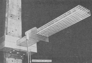
FIG. 1. Small-scale representation of engine-loading case.
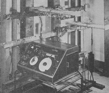
FIG. 2. Strain-gage system for engine-loading case.
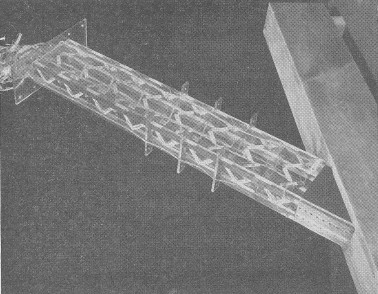
FIG. 3. Specimen representing simple sweepback.
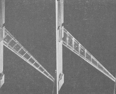
FIG. 4. Sweptback wing — comparison of "aerodynamic" and "structural" ribs.
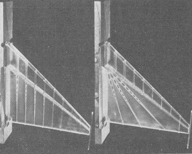
FIG. 5. Delta wing — comparison of fore-and-aft and radial trailing ribs.
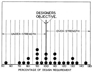
FIG. 6. Distribution of strength of wing systems as delivered.
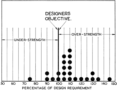
FIG. 7. Distribution of strength on completion of modification program.
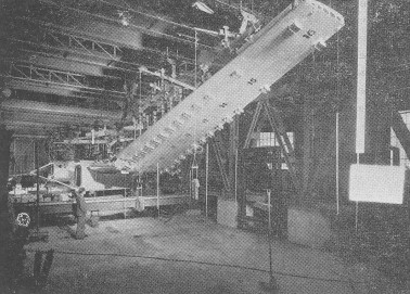
FIG. 8. A typical test to destruction.
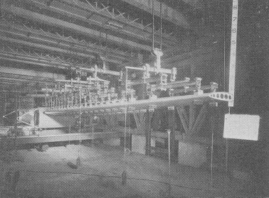
FIG. 9. Use of lever systems with several strainers.
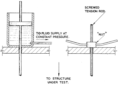
FIG. 10. Diagrammatic representation of reversible and irreversible strainers.
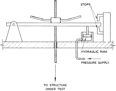
FIG. 11. Principle of the compound strainer (R.A.E. type).
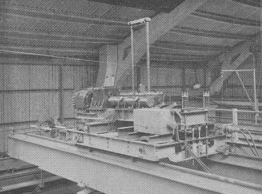
FIG. 12. Electrically-driven compound strainer (R.A.E.)
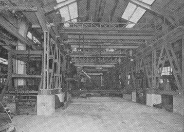
FIG. 13. End view of R.A.E. "Cathedral" test frame.
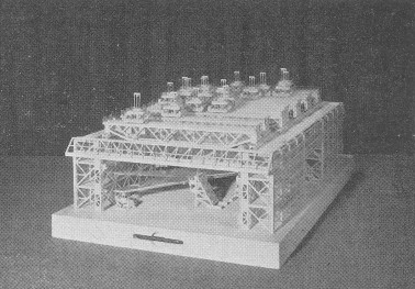
FIG. 14. Model of large test frame — 200 by 100 by 55 ft. internal dimensions.
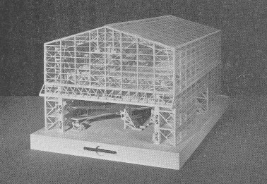
FIG. 15. Model of large test frame with building.
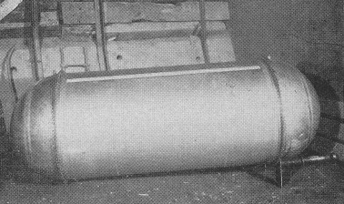
FIG. 16. Model pressure cabin before test (9 by 3 ft.).
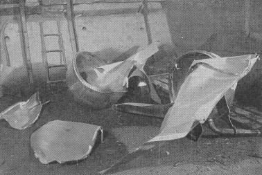
FIG. 17. Model pressure cabin after air test.
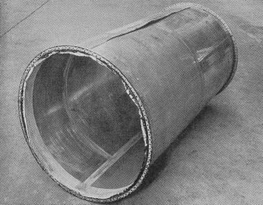
FIG. 18. Model pressure cabin (ends removed) after water test.
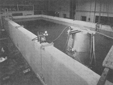
FIG. 19. R.A.E. strength-testing tank for pressure cabins.
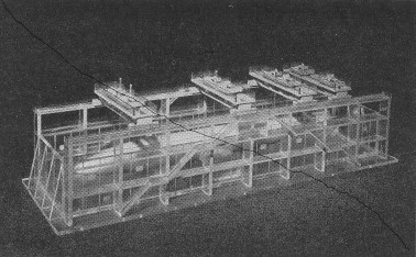
FIG. 20. Transparent model of submerged test frame for fuselages under combined loading.
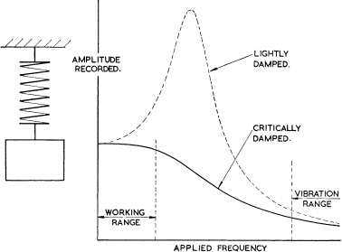
FIG. 21. Simple accelerometer and its response curves
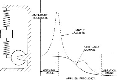
FIG. 22. Compound accelerometer and its response curves
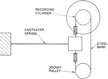
FIG. 23. Diagrammatic representation of actual accelerometer.
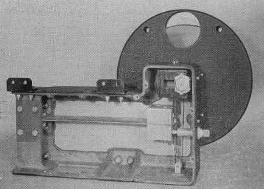
FIG. 24. Back view of accelerometer with cover plate removed.
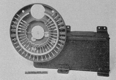
FIG. 25. Front view of accelerometer showing counting mechanism.
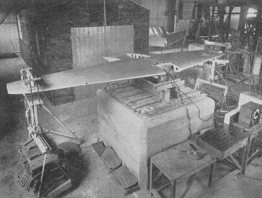
FIG. 26. Fatigue test on Meteor tailplane representing a wing.
REFERENCES*
* The references are relevant published papers by the author, but it should be noted that much of the work described is as yet unpublished.
[Ref. 1] Research Work in Aircraft Structures (1947), R. & M. of the A.R.C. No. 2327,1951.
[Ref. 2] Records of Major Strength Tests, R. & M. of the A.R.C. No. 2790. (Presented July, 1949; published 1952.)
[Ref. 3] The Principles of Aircraft Strength Testing, The Structural Engineer, November, 1948. (Paper read before Institute of Structural Engineers, November, 1948.)
[Ref. 4] Stability of an Aircraft in a Strength Test Frame, Jour. Roy. Aero. Soc., August, 1947.
[Ref. 5] Destructive Energy in Pressure Cabins, Jour. Roy. Aero. Soc., April, 1950.
[Ref. 6] Fatigue in Aircraft Structures, Jour. Roy. Aero. Soc., August, 1949. (Paper read before the Society in March, 1949.)
DISCUSSIONS OF THE LECTURE
Dr. Karl Arnstein, Vice-President, Goodyear Aircraft Corporation: Before I go ahead with my remarks I should like you to know that, when asked to discuss Dr. Walker's paper, I had good reason to believe that, as is customary, I would be one of a group of discussors. I, therefore, limited my prepared notes to a small section of Dr. Walker's work leaving the bulk of the discussion to my more ambitious colleagues only to find that tonight I am alone on the platform.
Dr. Walker has made an excellent presentation of the manner in which the many complex problems connected with the physicist's approach to aircraft structural research can be solved.
Out of the great wealth of information he has covered, I propose to discuss first the subject of testing of small-scale models, a field in which I have taken particular interest in the past.
The author's emphasis on the importance of careful selection of the elastic characteristics of simplified members in what he calls "Simplified Small-Scale Models" is well placed. Properly designed simplified small-scale models are of great value in the study of the underlying theory of a specific structural problem. One strikingly good example may be found in the model tests made in this country of a main frame of a large rigid airship of the "Hindenburg" class. This frame was composed of girders of approximately equal length located at the periphery of the circular hull section except at the bottom where the frame was built into a deep truss. The frame was braced by radial wires between diametrically opposite corners of the polygon. It was found that certain loads, particularly inwardly acting aerodynamic forces, would cause instability of the frame unless a definite amount of initial wire tension was maintained — an important piece of information that could not easily be gained by the mathematician's approach. On the other hand, I know of efforts where misleading results have been obtained from the use of simplified small-scale models because some elastic characteristics were erroneously considered nonessential and were neglected. The method of analysis with simplified small-scale models is only as good as the simplifying assumptions are, an observation that applies equally well to simplifying assumptions made in a mathematical approach.
Both approaches — through models and mathematics — have been used extensively in the solution of structural problems in the field of rigid airships where exhaustive testing of a full-size airship is not practical.
An example of the development of a mathematical approach can be obtained from a review of the history of the solution for the determination of the distribution of shear and bending stresses in an airship hull. In the early days, three different methods of analysis involving simplifying assumptions were tried: One used the beam theory as a basis; the second used the "method of transverse shears" as a starting point; and the third attempted to consider both, such as the one suggested by Hovgaard in 1922. There were good reasons to believe that the last approximation was the closest. However, it was not until 1938 that an exact solution was developed in the United States by the use of synthesis of type solutions involving difference equations expressed in trigonometric series which proved the reasonable accuracy of the Hovgaard approximation.
It is interesting to note that, prior to the availability of this exact theory, the degree of accuracy of the Hovgaard assumption was completely confirmed by tests on reduced-size true small-scale models, which were scaled down in correct elastic relationship with regard to axial stiffness, radial bending stiffness, and torsional stiffness. With an apology to Dr. Walker, I wish to state that my sympathies still rest very strongly with true small-scale model tests, which model tests I prefer even to measurements on prototype ships. This preference is based on the fact that in testing the prototype ship many strain gages are required at any section of a girder to obtain an accurate picture of the total load in the girder, while, by the use of models, the model members themselves can be designed so that they, in effect, become large strain gages for summing up the stresses imposed on the girders. Another point of interest is that the elastic range of such a model can be made to exceed the scaled-down prototype yield point, and, therefore, stresses may exceed the yield point in some members without damaging the model.
While there are many applications for which models can be used, their use is not recommended in the field of design of joints. It is our practice to test full-scale specimens, for the greatest difficulty in joint design is that some portion of the joint is apt to pick up loads for which it is not designed. Consequently, any simplification of a joint may cause misleading results.
Reviewing the available methods of analysis, we are reminded of the expression "many roads lead to Rome." This is also true for engineers seeking the answer to any one of their many problems. It is my opinion that every engineer should take the road with which he is most familiar and on which he has developed his greatest skill, whether it be the approach by simplified small-scale models, by true complete small-scale models, or by one of the many approaches of mathematics. We are greatly obligated to Dr. Walker for pointing out to us a road not very widely known or used which offers a new and speedy solution to certain problems.
Another remark of Dr. Walker's which interested me was his opinion that "the most efficient designs are most likely to be obtained when the designer deliberately takes a few chances and relies on strength tests to detect any weakness" and that "structures that failed prematurely in the first test were ultimately among the most efficient of them all."
Procedures of this kind were particularly indicated in the early days of aircraft construction, where great care was necessary in order to obtain a sufficiently light structure, since only inefficient materials were available.
When Count Zeppelin submitted his airship design to the Prussian Academy of Science about 60 years ago, he was told that an airship could not lift its own weight if it were to be designed strong enough to withstand any breeze of consequence. The Count succeeded in his work only by taking, not a few, but a great many chances. Consequently, he had a right to believe that the useful lift benefited from the amount of our scientific ignorance and that the useful lift deteriorated with the increased application of scientifically not fully digested information. He considered an airship overweight when it returned from its first trial flight without structural failure.
It is still true today that the greatest advances are made by lessons learned from failure.
In conclusion, I wish to emphasize that Dr. Walker's paper presents some of the important problems confronting the practical designer and gives the status of our knowledge regarding their solutions in an interesting way without the use of obscuring theoretical discussions. The author's beliefs and experience deserve careful study by every practical aircraft designer.
A. B. Callender, Supervisor — Structures Test Laboratory, Glenn L. Martin Company: Dr. Walker's paper is most successful in pointing out basic aspects of aircraft structural testing, this in itself being no mean task with respect to a field of engineering which deals in the main, with problems involving one specially tailored job after another. In addition, he is deserving of a vote of thanks from all of the structural test engineers in the airplane industry for presenting their story so expertly. This important branch of aircraft work merits more publicity than it is usually accorded, among other reasons, because of the competition it faces from newer fields of activity for interest and attention from young engineering graduates.
The presentation of test results on a large number of wings is of great interest. We find that we have more or less subscribed in recent years to the design philosophy expressed by Dr. Walker. The same trends from old to new designs are evident as indicated by the tests (shown in Table 1) carried out at The Glenn L. Martin Company over a period of 12 years. The wing specimens which failed to meet the design requirement the first time were able to be modified and retested successfully without an excessive amount of trouble. However, it is apparent that a point of diminishing returns is being approached wherein design efficiencies for weight- or cost-savings have to be balanced against modification difficulties, retests, and possible production schedule delays.
Table 1 Wing Specimens
| Wing | Year | Percent of Design Requirement Attained in Original Static Test (%) | Percent of Design Requirement Attained in Retest After Modification (%) |
| A | 1939 | 138 |
|
| B | 1942 | 123 |
|
| C | 1943 | 107 |
|
| D | 1945 | 94 | 108 (no failure) |
| E | 1947 | 100 |
|
| F | 1947 | 94 | 108 (no failure) |
| G | 1951 | 90 | Test not complete |
|
The section of the paper dealing with aircraft fatigue presents an excellent summary of the problem from the structural testing standpoint. We hope that Dr. Walker will be able to publish more information on the tests of the "Meteor" tail planes when it becomes available. It would be of interest to those working in this field if the lecturer would care to outline briefly the background of his selection of plus or minus 7.5 per cent design ultimate alternating load and 2,000,000 cycles as a reasonable compromise for a service-life test. An alternating load of 7.5 per cent design ultimate on a 4.5g airplane is approximately one-third g. If, in approaching this admittedly tenuous proposition, the frequently mentioned Cumulative Damage theory is accepted as a criterion for estimating the load level producing the most damage, the magnitude generally seems to turn out somewhat higher than Dr. Walker's figure, perhaps on the order of five-eights g or three-quarters g.
It is becoming evident that in the not too distant future some structural tests on components may have to be made under elevated temperature conditions. The problems presented by this development will open up a broad new field of activity in experimental aircraft structural research wherein different technical knowledge and much ingenuity will have to be exercised by the test engineers. Recent investigations indicate that, for representation of transient temperature effects at least, the best lines of approach may lie in the directions of induction heating or radiant heating. One aspect of this development which is quite apparent is that the designers and interested agencies will have to accept much more extensive test compromises with respect to load simulation in combination with temperature simulation than they have been accustomed to when the matter is one of load simulation alone.
L. M. Hitchcock, Staff Engineer — Structures, Boeing Airplane Company: It is with interest that we learn of the small-scale model testing being accomplished in Great Britain. A parallel development has recently been in progress at the Boeing Airplane Company. It was begun for the same reasons that prompted the Royal Aeronautical Establishment to use these models as vehicles of structural research. It is believed that the most fertile fields for this method of research lie chiefly in determining load distributions and material effectiveness in complex structures not lending themselves to ready analysis and in making comparative efficiency checks of various types of structural design.
With reference to strength testing of complete aircraft, Boeing policy in the past several years has been to static-test complete airplane structures of each new production type — normally the first airplane from the production line. Static tests of prototype or experimental models are not, in general, required except for miscellaneous panel and fitting tests and proof tests of control systems. Dr. Walker has indicated that it is common practice in the case of large aircraft to test wing and fuselage separately. We found in planning static tests for the B-47 that it was difficult and impractical to separate the wing and body tests for a swept-wing airplane because the critical condition for the inner wing was also critical for the fuselage center section. Therefore, the B-47 wing and body were tested concurrently for the most critical design condition in order to ensure proper distribution of the stresses to each part of the structure including any interaction effects.
In our experiences of static testing airplanes, we have made extensive use of electric strain gages for both control of the test and check of the designer's assumptions of load distribution. In the test of the B-47 airplane, 1,500 gages were used. These gages were read at each load increment, and the gauges at critical locations were watched continuously to help guard against major failure. As many as 400 gauges were read and plotted during each load increment for a major test. These gages proved invaluable in explaining the causes of any failure that occurred and in selecting the best way of increasing the strength of the airplane if desired.
Our history of initial failures in static testing is in general agreement with Dr. Walker's chart, although on wing primary structure our scatter has been in the order of 80 to 120 per cent of required ultimate strength. We have lost or destroyed two wings because of catastrophic failure below 100 per cent of design load: One wing failed at 92 per cent and the other failed at 95 per cent. We required a complete new wing for the test in which failure occurred at 92 per cent. However, the test of the other airplane wing to 95 per cent was considered proof of 100 per cent after determining the reason for, and the location of, failure and incorporating the structural changes considered necessary for 100 per cent strength.
We have been concerned with the trend in recent years to design airplanes with an absolute minimum in structural weight and also with the use of less ductile materials, which have a tendency to produce more scatter on the side below 100 per cent. Also, if several 100 per cent tests are to be performed on a particular component, the problem of local distortions occurring in one test to 100 per cent may influence the stress distribution in a test for another condition to the extent of causing premature failure below 100 per cent. In addition, any local failures in the range of 95 per cent to 100 per cent are more likely to induce complete failure of the structure, since there is little reserve in immediately adjacent structure to absorb any resulting redistribution of load. We have therefore considered testing structures to 95 per cent instead of 100 per cent for all tests on each structural component except for the final test to destruction. This manner of testing relies upon the destruction test substantiating our methods of stress analysis. We then have reasonable assurance that all other conditions tested to 95 per cent can be evaluated as to their ultimate strength. This approach, of course, is primarily directed toward saving of calendar time in the test program and reducing costs of replacement of structures by eliminating those few failures that might occur between 95 and 100 per cent. Structural changes required for airplanes in production must be determined as early as possible so that the least number of production airplanes will be affected.
With regard to the philosophy of deliberately designing structures by taking calculated risks, it has not been Boeing's policy to follow this course. We have enough trouble with premature failures due to improper detail design and errors without adding the risk of further delays and structural changes that might be required because of such a policy. Depending upon the quantity of production airplanes being produced, this can have a far-reaching effect upon rework of airplanes in the factory or possibly in the field, I might add that not too long after static tests are completed, the problem of airplane growth usually faces us., To my mind, it is preferable to design to scratch on the basis of minimum guaranteed properties and hope to demonstrate by static tests that the airplane has excess strength that can be utilized in permitting airplane growth rather than end up with a structure that might reduce permissible gross weights below the design value. In this regard we attempt to learn as much as possible about the strength of various sections or components of each major structure by progressive destruction tests. For example, the ultimate strength of the B-47 wing was obtained at three locations along the span.
Dr. Walker's discussion of the universal test frame is convincing for the case of a central test facility that is used to conduct tests on many types of airplanes. The initial high cost of installation is justified in view of the saving in setup time and man-hours for a number of static test airplanes and the probable high utilization of the test frame. However, if the tests are conducted at the manufacturer's plant, the initial expenditure for a static test facility may be of a considerably lower magnitude, since substantially less flexibility is required.
In the considerations of testing of large aircraft at a central testing agency in contrast to testing at a manufacturer's location, we must consider the cost involved in preparation of the static test airplane for flight to the central testing agency, the delays in the test program caused by preparation of the airplane for flight, and the additional delays and costs in the test program if extensive repairs or replacement of major components are required away from the contractor's plant. It is also possible that premature failures in tests of large aircraft will require replacement of major components that cannot be shipped from distant points for continuation of the test program.
In addition to the above items that affect the timing of changes required on production airplanes, we also have to consider the advantages gained by the manufacturer's structural engineers in witnessing static tests conducted at the contractor's plant. A considerable amount of this experience is lost if the tests are performed at a central test facility, because a large number of design engineers cannot be spared to witness these tests.
Testing of pressure cabins can indeed be disastrous. In the pressure test of the B-29 airplane, the complete nose section failed, as shown in Fig. A. This has been the exception rather than the rule because of our basic design policy for pressure structures. Because of fatigue considerations, it has been our practice to provide strength in excess of that required by the usual factors of safety on the static load. Thus, in the test program this fatigue reserve is reasonable insurance against primary structural failure. Protection from failure of doors and windows is provided, since these are the sources of most of our troubles in pressure sections.
The difficulty attached to a program submerging a full-scale pressure cabin of a large airplane into water and pressure testing is so great without special facilities that at present no such test procedure is contemplated at Boeing.
The counting accelerometer discussed by Dr. Walker is an interesting development with several ingenious features incorporated to reduce (using Dr. Walker's words) "the danger of producing too much information." This raises a question fundamental to experimental work of all kinds. Should we develop instrumentation purposely to exclude information that appears at the moment to be superfluous? The N.A.C.A. V-g recorder is a case in point. When this instrument was originally designed, the need for statistical study of accelerations significantly less than the extreme values was not generally realized. Accordingly, a device was conceived which, intentionally or not, obscured all data in regimes not then of immediate interest. We now look back on the data recorded in those thousands of flight-hours and wish we had been smart enough to anticipate our present intense interest in the statistical characteristics of the lesser accelerations. In fact, it is the limiting characteristics of the V-g recorder which have made necessary the reinstrumentation of further aircraft with Dr. Walker's acceleration counter. Even this instrument will give little if any direct information on airplane gross weight, altitude, and air speed at the instant of encountering the acceleration, gust gradient distance, and other factors of major importance to various aspects of the pressing structural design problems. I should like to suggest a diametrically opposite approach to problems requiring experimental study.
It would seem more desirable in experimental study to design instrumentation to record as completely as practical all factors of likely interest with regard to the particular subject. Having thus obtained a permanent record that may include information extraneous to some present pressing problem, it becomes a matter of applying ingenuity to the development of data reduction techniques. Later, when other aspects of the subject are of interest, the same experimental records can be reanalyzed to provide additional useful information without the delays incident to creating new specialized instrumentation, obtaining necessary program coordination, and then waiting the time necessary to accumulate statistically significant data samples.
In addition, I should like to venture the opinion that any high-frequency accelerations of magnitudes near the order as the lower frequencies for which the instrument was designed would be of extreme significance to the fatigue problem if they were transmitted through the structure. While the amplitude of motion required to produce a given acceleration is inversely proportional to the square of the frequency, the shear and bending stresses for a given amplitude are higher for the higher modes because of the associated more complex mode shapes. If these higher frequency accelerations are vibrations in the usual sense rather than the structural response to some transient external excitations, they may be of even greater significance because of their tendency to be ever present.
The tests of the Meteor tail planes are of considerable interest, and at such time as the information is made available it should contribute considerably to basic data on fatigue characteristics of structures. It is noted that the fatigue tests have been conducted at + 15° and -30°C. We wonder if the Royal Aeronautical Establishment plans to conduct tests on major components at elevated temperatures.
We agree with the comment that detail design of structural joints is a most important factor from a fatigue standpoint and that improvement in their design is the most expeditious method of obtaining increased fatigue life. Dr. Walker does not mention the comparative fatigue properties of various high-strength aluminum alloys. Our own tests, as well as other data, show that increased fatigue life can also be obtained by choice of material, such as usage of 24ST instead of 75ST. This is considered particularly important when tension material of a structural component is concentrated in one or two members.
The preloading of tension loaded bolts by the usage of nut-tightening torques is universally accepted as a method of reducing the alternating stress in the bolt. The proposed usage of high coefficient of expansion steel bolts to reduce the effect of low temperature slackening of the bolt tension is novel. We would be interested in knowing if special steel bolts have been evaluated for this application. I would presume that Dr. Walker is familiar with our practice of using bolts with threads rolled after heat-treatment with the attendant increase in fatigue life.
The amount of interference used in the interference fit bolted joint tests would be of interest. The tests conducted by Battelle Memorial Institute for the N.A.C.A. as reported in N.A.C.A. Technical Note No. 1030, using bolt clearances from -0.0005 to +0.050 in., showed no clearly defined effect on the fatigue strength of bolted lap joints from bolt clearance. It would be presumed that the lecturer's data were based on tests of considerably higher interferences. We would be concerned as to the possibility of stress corrosion with the use of high interference fits. However, interference fits possibly tend to alleviate the problem of fretting corrosion which has occurred on bolted connections with clearance holes. With regard to bolted connections, has any work been done on relative fatigue life of bolted versus redux connections?
Dr. Walker has indicated that an alternating load of 7.5 per cent of the design ultimate provides a good basis for the study of wing fatigue life. Our studies also show that this general region of alternating load for a four-factor airplane causes the major portion of fatigue damage in service. However, this is based on cumulative damage theory and published data on gust frequency.
N. J. Hoff, Head, Department of Aeronautical Engineering and Applied Mechanics, Polytechnic Institute of Brooklyn: Perhaps the most interesting idea brought up by Dr. Walker is the distinction he makes between the theoretical and the experimental approaches to research. I should like to quote his statement that "the experimental approach is more scientific than some might suppose, and it does not lead anywhere unless it is closely related to theory." This may sound strange to those experimentalists who still believe that the only purpose of testing is the measurement of the failing load of a structure. Dr. Walker's lecture illustrates clearly the great amount of theoretical knowledge that is required nowadays in order to plan tests, design test rigs, develop measuring instruments, and interpret the results obtained. It is safe to say that in reality there is little difference between theory and experiment. The theoretician who disregards experiment engages in mathematical deductions from first principles established by experimentalists decades or centuries ago and does not admit the possibility that present-day experimenters may add to or modify these principles. The experimental man who disregards theory simply puts his own personal experience above the fund of knowledge collected and ordered into a consistent system by great men who lived before him. Sound progress is possible only if theory and experiment merge as they do in this Wright Brothers Lecture, even though the emphasis in it is on the experimental approach as signified by the title.
One of Dr. Walker's great contributions to the development of our knowledge of structural behavior is his analysis of force control in testing. The design of improved strainers followed from this work, which in turn permitted the construction of a test frame of the efficiency and size of the "Cathedral." Not far from Farnborough in the south of England, tasks of a similar magnitude were accomplished by churchmen hundreds of years ago when they built cathedrals of unrivalled beauty dedicated to purposes different from those of Dr. Walker's Cathedral.
Another favorite subject of the lecturer is fatigue. His words on this topic inevitably recall that unparalleled source book of information on fatigue written by Nevil Shute entitled No Highway. At the time the book was written, there was only one chief of structures at Farnborough; his name was not Scott but Walker. Dr. Scott's efforts were directed toward merging the purposes of scientific research with the practical requirements of airplane construction and operation. He had to fight the group of research men who were characterized in the book as follows:
"There comes a time when the research worker, disappointed in promotion and secure in his old age if he avoids blotting his copybook, becomes detached from all reality. He tends to lose interest in the practical application of his work to the design of aeroplanes, and turns more and more to the ethereal realms of mathematical theory; as bodily weakness gradually puts an end to physical adventure he turns readily to the adventure of the mind, to the purest realms of thought where in the nature of things no unpleasant consequences can follow if he makes a mistake"
Judging from this Fifteenth Wright Brothers Lecture, Dr. Walker has been singularly successful in minimizing this kind of thinking in his group and has obtained results that are theoretically interesting, as well as useful in practice.
Paul Kuhn, Langley Aeronautical Laboratory, N.A.C.A.: Dr. Walker has presented a survey of structural research methods and results which is bound to be of great interest to anybody concerned with such work. I should like to make some comments on those phases of the lecture that fall within the sphere of N.A.C.A. activities.
First of all, I want to congratulate Dr. Walker and his staff on the interesting and useful work with plastic models. Aircraft structural designers are confronted nowadays with many difficult problems of which delta wings are one example. There is little theory for such structures, even for the sample case of a pure shell, let alone the much more complex case where the shell structure is heavily modified by adding spars and heavy ribs to take care of a landing gear, for instance. For such structures, plastic models can quickly provide answers that are much more reliable than those obtained by means of arbitrary assumptions. There is at least one case on record where a bad assumption led to a 30 per cent error, with serious consequences. There are some research men and some designers who look askance at plastic models. I hope sincerely that Dr. Walker's lecture will be instrumental in securing for such model tests the attention they deserve.
Dr. Walker mentioned a comparison between what he called aerodynamic ribs and structural ribs in swept wings. Similar comparative tests have also been made by the N.A.C.A. The differences were found to be as small as those mentioned in the lecture — of the order of 5 to 7 per cent — but in favor of the aerodynamic ribs. As far as bending deflections are concerned, this result agrees well with that estimated by elementary theory if one takes into account what civil engineers call participation stresses — that is to say, the contribution made by the inclined ribs to the moment of inertia of the beam. In the light of this experience, the results quoted by Dr. Walker are a little surprising, and it may be prudent to interpret differences of less than 10 per cent with caution until the test techniques employed on plastic models are more fully developed.
Somewhat surprising, also, but for a different reason, is the first test mentioned — a wing with overhung engines. It would seem that a simplified model test was hardly necessary, particularly after a full-scale test had been made, because a theory of bulkhead flexibility was established some time ago, and one or two reports published in England dealt exclusively with this problem. Is this, perhaps, another case of a prophet being without honor in his own country, or was the specific source of trouble one not covered by the existing theory?
Dr. Walker mentioned as a general conclusion from full-scale tests that the most common cause of premature failure is a stress-diffusion problem. I should like to underscore this remark heavily and hope that it receives full attention. In the past, there was some justification for treating such problems rather lightly in design. However, hidden factors of safety are being eliminated more and more, and the materials are becoming less ductile. As a result, stress diffusion problems have become extremely important indeed in static strength; they are, of course, also a prime source of trouble in fatigue.
The counting accelerometer described in the lecture embodies an ingenious approach to the difficult problem of eliminating extraneous vibration. I wonder if Dr. Walker would care to say a few words on the intended use of this instrument. It will evidently give a record of the load history of the airplane on which it is installed; this record might be used to estimate the remaining fatigue life of the structure. However, the application of the records to the design of new airplanes would seem to be rather uncertain, because the loads experienced are directly proportional to the speed, of the airplane, and information on the speed is not obtained.
The fatigue tests on tail planes are also interesting, but they prompt another question. Our predictions of fatigue life are highly uncertain at present. It appears that some fundamental .work has been done in England which promises to eliminate this vexatious problem. I wonder when Dr. Walker expects to be able to persuade the originator of this theory to publish it. I am referring to the theory of fatigue developed by that eminent staff member of the R.A.E., well known on both sides of the Atlantic, Mr. Honey.
J. F. McBrearty, Structures Division Engineer, Lockheed Aircraft Corporation: It is a rare occasion indeed when an engineering profession is favored with a thorough and lucid inventory of the major accomplishments and problems in that field such as Dr. Walker has assembled in this Wright Brothers Lecture for 1951. The aircraft structural engineering profession is indebted to him for the insight and practical touch with which he has seasoned this paper. In addition to important concepts of engineering philosophy and design policy, he has interlaced this lecture with most of the important down-to-earth facts discovered in the course of structural research and testing in recent years.
One of the most important, and perhaps controversial, points discussed by Dr. Walker is the philosophy of designing a structure "on the light side" and then developing suitable reinforcement in static tests, and I would like to comment on this one aspect of Dr. Walker's subject. It is true that this approach has become more widely accepted in recent years due largely to increased demand for weight economy and to more and more complicated structures, and yet I feel that this approach can be carried too far for our own good.
In the first place it must be remembered that the design condition and the corresponding test does not constitute an end in itself but is merely the means to an end — that end is to produce a structure that will be adequate in service. It is not always true that the design conditions are just the necessary and sufficient criteria to result in a satisfactory service structure, and all too often the structural elements that show distress in static tests are not at all the elements that prove to be the Achilles' Heel in service. Frequently, 100 per cent of some design condition in a static test is viewed as a "magic number" and exact achievement of it assumed synonymous with the structure living happily ever after. I wish this was true — certainly the life of the structural designer would be a happier one if it were — but it seldom is. Design conditions are rarely so rational and realistic and often are completely arbitrary, and in any case an arbitrary safety factor is superimposed on any condition, however realistic. Consequently, I feel that a good stress analysis frequently is the better index of structural adequacy and would be equally fruitful in minimizing weight if the stress analyst were permitted to assume the very things that are taken for granted in a static destruction test, such as above average material properties, favorable load distributions, and so forth.
It has been our experience in many cases that the stress analysis, moreover, is a better indicator of troublesome details than is a static test, which often glosses over stress raisers and the like by plastic relief. Thus, it should be made clear that the static test of the structure is a supplement to, and not a substitute for, a thorough and careful stress analysis and does not relieve the structural designer of the necessity for applying experienced judgment to preclude service troubles.
Perhaps the most practical consideration in this approach to structural development is the timing. If the structural test isn't early enough in the schedule, then it produces none of the advantages yet all of the disadvantages of this procedure. The attractiveness of the development by test scheme fades if the test is going on after all the production tooling is built and long lines of production articles are in the jigs or (as sometimes the case) even in the skies. Thus, while this approach may be economical and practical for the design of a prototype or small quantity contract, it is doubtful that it is the wise course to pursue when a design is scheduled into early production. In any event great emphasis should be given to providing the structural test laboratory with facilities for the rapid construction of test structures and the speedy conduct of the tests. Dr. Walker has described some of the advances made in this latter field, and they are certainly to be encouraged. No less important, however, is the problem of getting the test data and report into the hands of the designer who uses them, and, consequently, there should be more and more mechanical aids to this phase of the work. Automatic strain recording devices, mechanical and electronic computing machinery, and dictaphone equipment should be employed to minimize the interval that the research results spend between production and delivery to the consumer — the designer.
It is believed that structural development by test is here to stay and that it enables the designer to exploit at the outset much of the airplane "stretch" that heretofore was a slow process spread over the years as the airplane demonstrated in service its further capabilities. The designer, however, must be discreet in his employment of this powerful method and not forget the pitfalls mentioned here.
Once again, I wish to commend Dr. Walker for presenting us with a most informative lecture for which all aircraft structural engineers should indeed be grateful.
Walter Ramberg, Chief, Mechanical Division, National Bureau of Standards: Many of us in the field of structural testing will envy Doctor Walker his impressive "cathedral" test frame for applying vertical loads to full size wings and fuselages of aircraft and will wish him all success in obtaining for his laboratory the still more ambitious test frame described by the models in Fig. 14 and Fig. 15.
Facilities such as these give the Royal Aircraft Establishment an exceptional opportunity to collect data on the modes of failure under static load of aircraft of many different types. As a result, Doctor Walker and his associates should be in an excellent position to answer a question that has bothered all those who have had to rely on analyses and tests of relatively small components in estimating the strength of the full size structure. The question is simply to what extent can one rely on careful design and on tests of small components? Or, to put it quantitatively, in what percentage of the tests of complete structures was the failure due to a "general instability" in which the entire structure was involved rather than a local weakness that could and should have been caught before the test of the complete structure? Fig. 6 and Fig. 7 of the paper indicate graphically the improvement that results from tests of complete wings and fuselages, but the failures are not separated into those that might have been prevented by more careful design and construction and those that could not have been predicted. Doctor Walker may recall that the aircraft structures people became seriously worried about "general instability" following the tests of reinforced cylindrical shells conducted by von Karman, Dunn, and Sechler at the California Institute of Technology about 10 years ago (see for instance N.A.C.A. Technical Notes 905-911). These showed convincingly that it was sometimes unsafe to neglect the complicated interactions between different portions of a stressed-skin aircraft structure in estimating its margin of safety against instability.
This discusser would like to compliment Doctor Walker upon the development by his colleague, James Taylor, of a counting accelerometer that appears to function without a single electronic component in it. This should be a challenge to some of our American test engineers who have become prone to capitulate to the electronic engineers before fully exercising their ingenuity in devising a purely mechanical instrument and making it work.
E. E. Sechler, Professor of Aeronautics, California Institute of Technology: In these days of new and elaborate computational methods and machines, it is refreshing to hear so eminent a scientist as Dr. Walker advocate not only the continued use, but the expansion of, experimental techniques for the solution of some of the complex problems of aircraft design. It is particularly fitting that the experimental method should be re-emphasized in a Wright Brothers lecture, since it was essentially through experimentation that the Wright Brothers were finally able to build and fly their history making airplane.
So many of our young engineers grow up with the belief that if, by some magical means, a problem can be fed to an analog or digital computer, the answer that comes forth in a matter of seconds will be the solution to end all of their difficulties. Unfortunately, this is not true, primarily because the complex computing machine, with all of its capabilities, has no power to modify assumptions based upon actual experience as to the manner in which a structure will react under various loading and restraint conditions.
Experimentation such as that discussed by Dr. Walker is, in many instances, the only way in which proper assumptions as to the behavior of complex structures can be made. Even when full-scale assemblies of metal structures are tested, the designer is frequently limited to visual observations on the outer portions of the assembly and must rely upon remote reading instruments to give limited information as to the behavior of internal elements. The use of optically transparent material, such as Xylonite, for models often reveals interaction effects that would not otherwise have been taken into consideration.
I do not wish to give the impression that the use of computers should be eliminated or even decreased.
What is required is the use of all available methods to obtain the best possible design for a given aircraft structure. This will entail the integrated use of the highest level theoretical knowledge, the best computational techniques, and the fullest possible application of experimental methods. Dr. Walker's paper shows that the experimental method can well take its proper place in this trinity of tools for design analysis.
C. R. Strang, Strength Engineer, Douglas Aircraft Company, Inc.: Someone has said that nobody believes a theoretical analysis except the analyst who prepared it, while everybody believes a test except the test engineer who prepared it. This too true statement aptly conveys the idea that tests are convincing regardless. The admirable thing in Dr. Walker's philosophy is precisely that it never occurs to him to test for the test's own sake but that there is always a purpose. Dr. Walker has effectively shown that the experimental method is now as important as it ever was and that the situation will probably continue that way. At least in the foreseeable future, there are certain to be radical changes in structural configuration from one model to the next, as well as a constant pressure on the designer to hold structural weight to the minimum. This means no letup in the need for tests to prove theoretical strength analyses.
The test methods and testing philosophy of the manufacturer of transport air frames are considerably different from those of an agency such as the Royal Aeronautical Establishment. For example, where the latter is able to concentrate on destruction tests of complete airplanes, the manufacturer is forced by considerations of timing and economy to do most of the destruction testing on components of the structure (see Figs. B-F) during the design stage of the airplane, followed by a limit load test on the complete airplane. This procedure is not all that might be desired, but it has resulted in some highly successful models. In the following discussion of our test methods it will be seen that there are other differences in technique, which should not necessarily be interpreted as adverse criticism of either one.
Our custom is to use hydraulic tension cylinders as much as possible to apply and measure the test loads.
The jacks are manifolded together in the minimum number of groups, each at a common pressure, which will result in the test specimen being stable. A conventional system of levers is used to make this possible. The system is such that, if one part of the structure fails, the remaining loads will be relieved without, it is hoped, any excessive dynamic forces. Incidentally, the Australian Council for Scientific and Industrial Research has published a simple and efficient method of arranging linkage systems to obtain such common pressure groups of jacks. [Report SM52 by W. W. Johnstone, "Strength Testing of Aircraft Wings — A Review of Current Methods"] The all-hydraulic system of loading has the advantages of simplicity of installation and of operation, accuracy, and sensitive control. It stores practically no energy within itself during loading (providing no accumulators are incorporated), with the result that damage to the structure after failure is minimized.
The problem of handling large deflections is becoming more and more acute as wing spans increase, while relative wing thicknesses simultaneously decrease. In this case it seems that a combination of a screw jack with a moderate-size hydraulic jack would be more practical than a long-stroke jack by itself. For this purpose the mechanical and hydraulic jacks would probably be connected in series, rather than arranged as in the R.A.E. lever system.
Air-pressure tests of windows, astrodomes, and other glass or Plexiglas structures almost always result in violent failures with all evidence of the locality of the initial failure destroyed. This is due (in addition to the causes discussed by Mr. Walker) to the brittle nature of the structural material. Such structures, therefore, are ordinarily tested with water. Small pressure vessels of metal are most conveniently and safely tested in this manner also.
Recently, we tried out a variation of this technique in which we ran a vacuum (instead of positive pressure) test on a vessel. The specimen was a barrel-like enclosure for an auxiliary power plant. The water was drawn from the test specimen by means of a small rotary pump and was discharged into the tank in which the test specimen was submerged. A small volume of air, unexpectedly trapped in the specimen, expanded to a large volume when the pressure was reduced. Also, some of the air in solution in the water "boiled" out to further increase the volume. The net result was a more general type of failure than would have occurred if the air had been completely removed at the start of the test (Fig. C).
The failure of a fuselage under negative pressure is more violent than would be expected, as we learned at the end of a test program on a 15-ft. section of DC-6 fuselage from which the air was evacuated until the structure failed. The results of the "implosion" that occurred at -3.4 lbs. per sq. in. are shown in Fig. D and Fig. E.
For pressure testing of major fuselage sections we have favored air, rather than water, as the pressure medium for the following reasons:
(1) Using air, the structure is easily and quickly accessible for observation and for inspection and repair of damage during test.
(2) The structure is not so subject to corrosion. This is an important factor, since such test programs usually extend over a period of several months, and, in some cases, parts of the specimen will be used for structural development a year or more after completion of the original test. This phase of the problem is further aggravated by the use of magnesium alloys in the structure,
(3) The time, expense, and complication of the submerging tank are avoided.
Although we have found it more practical to use the air-pressure type of test, for the reasons already mentioned, we still have a great deal of healthy respect for the potential energy stored in a pressurized cabin and therefore take precautions to prevent injury to personnel or plant facilities. However, it has been our experience that it is possible to obtain a great deal of design information in a reasonable length of time by repeatedly pressurizing the structure, with air, to successively higher pressures, reworking the structure each time a weak point develops. A considerable portion of this part of the program is usually accounted for in developing the latches and seals for the doors. Usually, we try also to work in enough cycles of limit pressure to ensure that there are no details of the structure which are obviously deficient from the fatigue standpoint. When sufficient static and fatigue strength information has been obtained by this cut-and-try procedure, we are ready to determine the ultimate strength of the structure. As we all realize, the failure that is then obtained can be rather violent, although this is not invariably true.
Fig. F shows a pressure test on the forward section of a DC-6 fuselage. Fig. G and Fig. H show the final failure of this specimen. At 10 lbs. per sq. in., the vertical bulkhead immediately forward of the pilot's position blew out. The pieces were thrown into the nose-wheel well and were stopped after barely puncturing the nose cap. There was recently a more dramatic demonstration of the ability of a fuselage to hold together after explosive decompression. A DC-6 while in pressurized flight was cut almost in half by a propeller blade thrown from one of the engines. Except for one fatal heart attack brought about by the excitement, there were no injuries to passengers or crew, and the airplane was able to fly to the nearest airfield and land without further damage.
It is generally agreed that more accurate gust data, as well as a more suitable method of interpreting the atmospheric gust phenomenon and airplane response, are urgently needed. In the U.S. we are presently engaged in this study with V-g-h-instruments of N.A.C.A. origin. These instruments record time, altitude, speed, and e.g. acceleration of the airplane. Most of the existing data have been difficult to use because all of these variables have not been measured simultaneously.
The N.A.C.A. and the aircraft companies of this country have asked the commercial air lines, as well as the military, to cooperate in obtaining flight data with presently available and, later, improved recording instruments. In order to minimize the labor and delay in the reduction of the vast amount of data that would necessarily be collected, they have recommended that, as far as possible, the data reduction be mechanized.
While some repeated load testing of aircraft wing structures has been, and is being, done in this country, we feel that data from fatigue tests of small specimens and components can be used to good advantage. For the past 18 years we have been fatigue testing various types of specimens from simple riveted joints to full size wings and have been fairly successful in correlating the results of small specimen tests with those of tests of large complicated specimens. One of the test programs involving the 15-ft. fuselage specimens showed especially good correlation between the two types of tests. It had been suspected that the attachment of the fuselage frames to some of the stringers would be critical in fatigue because of repeated pressure cycles in the fuselage. Small specimens simulating the attachment conditions were tested in a fatigue machine with results that were believed to confirm this feeling. The full-scale test that followed duplicated the results of the smaller test. It was then a relatively simple matter to devise several improved attachment designs, to try them out with simple specimen fatigue tests, and, finally, to incorporate the best redesign on the production airplane. (See Fig. K.)
Dr. Walker has referred to the practical necessity of balancing economic considerations against design refinement for maximum fatigue strength in structural joints. We also feel that such costly steps as reaming holes to extremely close tolerances, shot peening, using relieving slots, etc., should be used only after all of the simpler design refinements have been exhausted. Fortunately, there are steps that can be taken to increase the fatigue strength of parts without requiring too skilled workmanship. For instance, it may be worthwhile to use bolts having threads rolled after heat-treatment, which gives much greater fatigue strength than ground or lathe-cut threaded bolts. This is illustrated in Fig. N. The effect of pretensioning of bolts that Dr. Walker referred to can also be seen on this figure. The test loads to which these bolt specimens were subjected were carefully controlled, "and the load ranges were constant during, the testing. It should not be implied, however, that this, increase in strength is indicative of what can be attained in an aircraft joint in service. Lab tests have shown that, after a few thousand cycles of loading, the pretensioning that had originally existed in the bolt decreases and may decrease to as little as one-half its value. Overhaul and maintenance checking every few thousand hours are the only preventative measures for the fatigue of major structural bolts in aircraft.
In summarizing the fatigue problem, we agree that we need more knowledge of the flight loads imposed on aircraft. We do have a reasonable knowledge of the effect of cumulative loading. We also have some success in correlating small laboratory coupons with full-scale tests. We can also, with a fair degree of accuracy, calculate or predict fatigue life and strength of test specimens from past experience and a wealth of data; but, as to the calculation of the life expectancy of an aircraft, little progress has been made. Fig. O, the form of which you have seen many times, shows in some degree the dispersion in laboratory test mortality data and service loading mortality. Mortality dispersion of the joint between the inner and outer wing panels of the DC-3 are plotted, using laboratory test data and actual service failure data. Life insurance company data on human mortality are also plotted for comparison. Mortality of the laboratory test specimens and of human life appears to follow a similar law, while that of airplane wing joints follows a different one. It is interesting that a calculation of the life of the part from the stress analysis and accepted gust frequency statistics revealed the part would never fail. Yet failure did occur in the form of skin cracking which is the most common type of fatigue cracking of light members. Serious? No, not when it takes 24,000 service-hours per airplane to develop cracks in 6 per cent of 920 wing joints.
Fatigue cracks characteristically develop slowly, and finding them is a matter of careful inspection. Here, then, is the essence of concern for the eventual structural integrity of the airplane. It is inevitably a matter of inspection and maintenance. It will always be so, no matter how the airplane is designed and built originally.
Discussion Figures
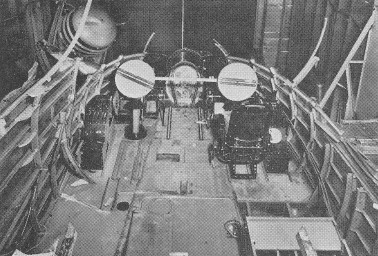
FIG. A. Pilot's compartment after pressure test XB-29.
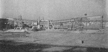
FIG. B. Section of the DC-4 wing set up for repeated load testing.
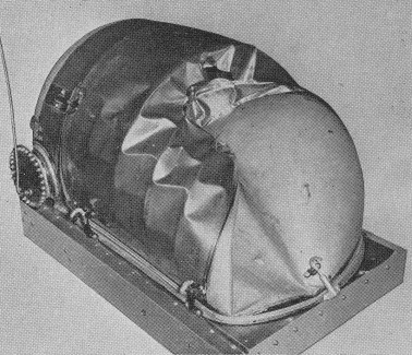
FIG. C. Auxiliary power-plant enclosure after failure due to external pressure.
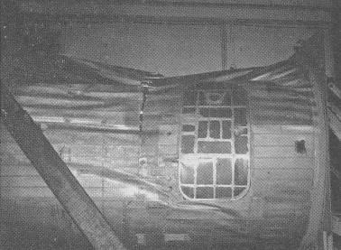
FIG. D. Test failure of a fuselage section due to external pressure.
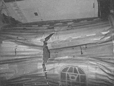
FIG. E. Test failure of a fuselage section due to external pressure.
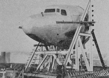
FIG. F. Pressure test setup for the forward section of the DC-6 fuselage.
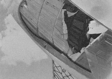
FIG. G. Details of the damage to the fuselage forward section caused by the pressure test.
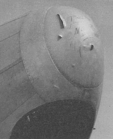
FIG. H. Details of the damage to the fuselage forward section caused by the pressure test.

FIG. I.
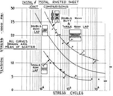
FIG. J.
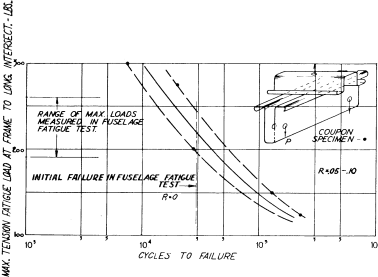
FIG. K. Load cycle diagram for the critical joint of both coupon specimen and fuselage test section.
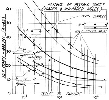
FIG. L.
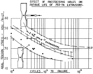
FIG. M.
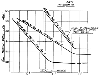
FIG. N.
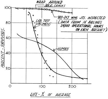
FIG. O.
REPLY TO DISCUSSIONS OF THE WRIGHT BROTHERS LECTURE*
P. B. WALKER**
Royal Aircraft Establishment
* Walker, P. B., The Experimental Approach to Aircraft Structural Research, Journal of the Aeronautical Sciences, Vol. 19, No. 3, p. 145, March, 1952.
** Head, Structures Department.
The discussions following the Wright Brothers Lecture have added much valuable material to the original paper. Though there are minor differences of opinion on some matters, the discussions as a whole are remarkable for the general measure of agreement on fundamentals. The comments which follow are mainly directed towards answering specific questions or in response to requests for further information.
Mr. A. B. Callender asks how the fatigue test criterion — an alternating load of 7.5 per cent of the design ultimate, applied two million times — was obtained. It is, of course, difficult to trace all the tentative processes leading to an empirical criterion, but there are a few points which may be of interest.
The single fatigue test has to represent a wide range of loading conditions, corresponding to an extensive working portion of the endurance (SN) curve. From this standpoint, the 7.5 per cent alternating load is chosen as being well placed in a sensitive region of the typical curve and as not calling for undue length of testing time. In addition, the criterion has to cover in a somewhat indefinable way the cumulative effect of mixed cycles. In this connection it is of interest to record that recent British calculations indicate that 7.5 per cent for the alternating load is a little on the high side theoretically, but not more so in practice than is required to give a reasonable working margin of fatigue strength. This conclusion is at variance with Mr. Callender's figures, though it is endorsed by a later speaker (Mr. Hitchcock).
It is intended that the complete criterion be modified as necessary with increasing experience or to meet special conditions. In general, it is simpler to alter the required number of cycles than the alternating load. The two million cycles stipulated is regarded as corresponding roughly to a life of 30,000 flying hours or about 10 years. Within reasonable limits, however, proportionate reduction is permissible when a shorter life is expected for reasons not concerned with fatigue. Adjustments are also to be expected when fatigue loading data are available for particular aircraft operating over particular routes. The original criterion was intended to set a conservative standard at which designers were advised to aim. Later experience, obtained since the lecture, indicates that the criterion may not always err on the side of safety.
Professor N. J. Hoff's comments are most encouraging. In a deliberate presentation of a case for greater recognition of experimental work in the structural field, there was a danger of appearing to minimise the value of mathematical and theoretical work. There is, of course, no conflict between the two branches of structural research, but it is good to have this view endorsed by an outstanding leader in theory of structures.
Mr. Paul Kuhn, whilst recognizing the value of small-scale work, expresses doubts as to its accuracy. I do not share these doubts. As stated in the original paper, the model work is not regarded as a method for absolute prediction of stresses in real structures, but British experience leads to the conclusion that it is reliable for comparative work such as the examples given in the paper.
On the question of comparison between "aerodynamic" and "structural" ribs, Mr. Kuhn gives N.A.C.A. results conflicting with those of R.A.E., and suggests that this discrepancy is an indication of the margin of experimental error. I would suggest some other explanation, though I cannot speak with certainty in the absence of detailed knowledge of the N.A.C.A. tests. The R.A.E, models had ribs designed to represent typical ribs as used on actual aircraft. Heavier ribs, especially ribs with heavy flanges, might behave differently; but in this event a direct comparison becomes difficult and results are open to different interpretations. According to R.A.E. calculations, moreover, the participation stresses mentioned by Mr. Kuhn are not significant for ordinary light ribs, and for heavy ribs become significant only at angles of sweepback exceeding 60°. The R.A.E. tests, incidentally, did not go beyond 45°.
Mr. Kuhn's suggestion that the engine loading effect could have been predicted from theoretical work already published in England is not strictly correct. The relevant portion of this work dealt only with a change of torque. The effect of the offset engine load is not so simple, and it is much greater than could have been accounted for by the then existing theory.
In reply to Mr. Kuhn's query about the future use of the counting accelerometer, it can be stated that this will be installed on as many aircraft as operators will tolerate. With increasing realization of the fatigue danger, it may well be on the way to becoming a piece of standard equipment for fitting to all civil and transport aircraft. The point about speed being significant as well as acceleration is fully appreciated, and is covered in my reply to Mr. Hitchcock.
Mr. Walter Ramberg raises some vital points about design and test interpretation which unfortunately cannot be treated adequately in brief comments. As I understand the term, "general instability" did not occur in any of the tests analyzed. Nevertheless, it does not follow that the only alternative was local weakness which "could and should have been caught before the test of the complete structure." Stress diffusion, as mentioned in the paper, and other allied effects often lead to premature failure of a structure whose components would have been regarded as satisfactory when treated individually.
As regards Mr. Ramberg's next point, it is not generally possible to make a clear-cut distinction between failures which could have been prevented by careful design and construction and those which could not have been predicted. In the first place, the economics of design comes into the picture. The prospects of predicting any form of failure depend upon the time, money, and effort that can be expended in design research and theoretical study. Without setting precise limits to these, it is impossible to divide premature failures generally into predictable and unpredictable classes. In the second place, it has to be borne in mind that the designer normally makes every endeavor to produce a satisfactory structure, and does not hesitate to make laborious calculations when these are thought to be necessary. The result is that — apart from the few unqualified mistakes — premature failure, when it occurs, frequently admits of no simple explanation and is attributable to a complexity of causes. Faced with such a situation, it becomes difficult for the structural specialist to say exactly what it is that the designer is supposed to have predicted.
Professor E. E. Sechler does a great service in giving a warning against unrestrained enthusiasm for analog and digital computing machines. Development in this field is extremely important, but must not be allowed to reduce interest in the direct experimental approach. The two approaches are not alternatives, and both increase in value when they are followed in parallel. Incidentally, in applying the Xylonite-model technique there are times when a model can almost be regarded as an analog machine rather than as a physical representation of a structure.
Mr. J. F. McBrearty appears to be seriously concerned at what he regards as the over-ready acceptance of the design philosophy by which structures are tested, broken, modified and re-tested as a matter of deliberate policy. I entirely agree with him in pointing out the dangers of unrestrained use of the principle which underlies this philosophy. As stated in my paper, it is possible to produce a structure that is altogether too weak, and beyond remedial action, whilst the time expended in repairs and re-tests might well become intolerable. I do not agree, however, that the principle is being misused to any appreciable extent. In Britain, the evidence indicates that a good practical compromise is being achieved, and I would have thought that much the same applies in America.
I entirely agree with Mr. McBrearty that testing is no substitute for a proper stress analysis. In my view, testing of a structure that has not been fully investigated theoretically is largely a waste of time, money, and effort. Testing is a safeguard against direct mistakes remaining undetected, but this is only part of its purpose. It should be regarded as a check on theory, of a kind which will benefit not only the particular aircraft tested but many others which follow.
Mr. L. M. Hitchcock's remarks on ordinary static strength testing are of great interest, and a welcome addition to my own records. There is only one point on which comment appears appropriate, and that concerns the advisability of having a central testing unit available to the whole country. The situation in U.S.A. is different from that in England owing to the much greater distances involved. Even in Britain, however, it is considered that the central unit should not operate in competition with industry, and that its contribution must be additional and complementary to industry's own effort. It is considered that there is a purpose to be served by a central advisory body in the strength testing field, but that such a body cannot function realistically without first-hand testing experience. Furthermore, there are long-term and uneconomic research projects which industry cannot normally be expected to undertake.
On the question of testing pressure cabins in water, I think Mr. Hitchcock overestimates the difficulties. Pressure testing equipment, whether permanent or improvised, is much more easily produced than might at first sight be expected. It is, moreover, not at all difficult to arrange fatigue tests to reproduce the raising and lowering of cabin pressure as occurring on aircraft in operational use. Successful fatigue experiments, in fact, have been made in the water tank illustrated in the paper.
The value of information additional to that given by the counting accelerometer is appreciated. There is a more elaborate version which records photographically speed, time, and altitude, as well as acceleration counts. This is necessarily heavier and more expensive than the simple one, but does not need to be fitted so frequently. It should be understood that, as Mr. Paul Kuhn stated, this additional information is required for the benefit of subsequent designs or for the same aircraft operating under different conditions. The simple version covers adequately the normal fatigue hazards of the particular aircraft on which it is fitted.
There are a number of direct queries put by Mr. Hitchcock on fatigue which can be answered briefly. (a) It is intended eventually to cover a range of both high and low temperatures in the testing programme for the Meteor tail plane, (b) As to the choice of materials, I prefer not to comment on the particular materials mentioned, but feel justified in saying that in future more consideration will have to be given to the fatigue properties of materials and less to ultimate static strength — at least for civil and transport aircraft, (c) There is a nickel-chromium steel (British Specification D.T.D.247) which has about the same coefficient of expansion as aluminum alloy. It appears to have been used at one time for dealing with a similar problem for engines, but is probably unsuitable for bolt manufacture. Research to discover a suitable steel might well be justified, (d) The interference fit found necessary to produce increased life of joints having steel bolts loaded in shear is approximately three thousandths of an inch for one-half in. and three-quarters in. diameter steel bolts. It is interesting to remark that as the negative tolerance is progressively increased from zero there is at first no significant change in fatigue life, but then the life increases rapidly to something of the order of 100 times.
Dr. Karl Arnstein's comments reached me later than the others, and there is only one specific point on which I would like to comment. It is true that scale-model work, just as mathematical analysis, cannot when directly applied be more accurate than the simplifying assumptions. The main object in using the models for comparative work as described in my paper, however, was to nullify most of the errors introduced by simplifications. With reasonable care these can usually be made to affect equally the two models that are being compared, and so bring out the differences relating to the one particular phenomenon or structural principle that is being studied.
I am grateful to Dr. Arnstein for his useful summary of the whole situation for present-day structural work. It is true that "many roads lead to Rome", and, while we should all study the methods of others, success is possible only with those methods in which we have gained confidence through direct experience.